
A millimeter wave single-channel control tr component
A single-channel, millimeter-wave technology, applied to radio wave measurement systems, instruments, etc., can solve problems such as difficulty in meeting demands, and achieve the effects of saving production costs, improving control accuracy, and good electromagnetic compatibility performance
Patent Information
- Authority / Receiving Office
- CN · China
- Patent Type
- Patents(China)
- Current Assignee / Owner
- Publication Date
- 2021-09-07
Smart Images
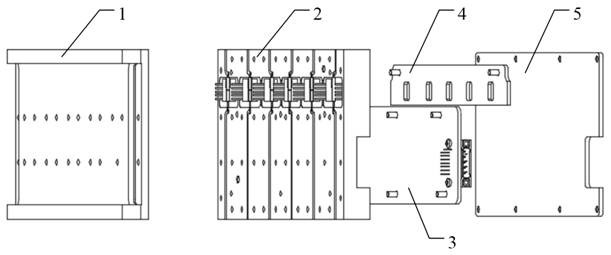
Figure 1 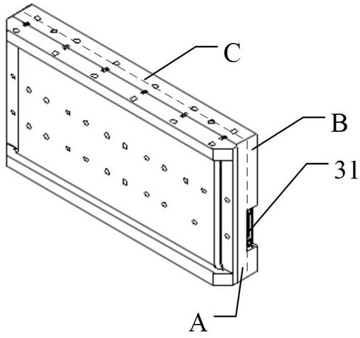
Figure 2 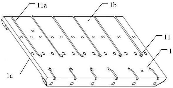
Figure 3
Abstract
Description
technical field
[0001] The invention relates to the field of millimeter-wave radar, in particular to a millimeter-wave single-channel control TR assembly. Background technique
[0002] Millimeter wave has the advantages of wide frequency band, short wavelength and high resolution. In recent years, it has developed rapidly in the fields of radar, communication, and remote sensing. As a key part of millimeter wave radar, the front end of millimeter wave antenna is more and more worthy of people's attention. focus on. As the core component of the millimeter-wave antenna front-end, the millimeter-wave TR component has higher and higher performance requirements. It is increasingly difficult for the current millimeter-wave TR component to meet the demand. Contents of the invention
[0003] The object of the present invention is to provide a millimeter-wave single-channel control TR assembly to improve the electromagnetic compatibility, control accuracy and reliability of the TR...
Examples
Embodiment 1
[0031] A millimeter-wave single-channel control TR component, see the attached Figure 1-7 , the TR component includes a component body, and the component body includes an upper side A and a lower side B. The upper side A and the lower side B are two parts divided by the component body from the middle part C. It should be noted that the " The middle part C" can be the middle of the component body, or other non-edge positions, as long as the electronic components in the upper side A and the electronic components in the lower side B can be isolated. Several groups of radio frequency structures are set on the upper side A of the component body, and the adjacent radio frequency structures are isolated from each other. The mutual isolation can be realized by setting metal plates, for example, to increase the isolation between channels. Each group of radio frequency structures includes a TR chip 21 , a VM chip 22 and a transmission line structure bonded to each other with gold wires...
Embodiment 2
[0035] This embodiment discloses the structure of the component body.
[0036] The component body includes an upper cavity 1 and a lower cavity 2, such as figure 1 ,3 , 4, the upper cavity 1 includes the upper surface 1a of the upper cavity and the lower surface 1b of the upper cavity, the upper surface 1a of the upper cavity and the lower surface 1b of the upper cavity are opposite; the lower cavity 2 includes The upper surface 2a of the lower cavity is opposite to the lower surface 2b of the lower cavity, and the upper surface 2a of the lower cavity is opposite to the lower surface 2b of the lower cavity. The lower surface 1b of the upper cavity is docked with the upper surface 2a of the lower cavity and connected together by screws, and the position is located on the upper side A of the component body. The transmission line structure is arranged between the lower surface 1b of the upper cavity and the upper surface 2a of the lower cavity. The VM chips 22 and TR chips 21 o...
Embodiment 3
[0040] This embodiment takes the design of 6 channels as an example (the number of other channels is designed in the same way), and discloses a W-band single-channel control TR component, such as Figure 1-7 As shown, the upper cavity 1 and the lower cavity 2 are included, the upper cavity 1 includes the upper surface 1a of the upper cavity and the lower surface 1b of the upper cavity, the upper surface 1a of the upper cavity and the lower surface 1b of the upper cavity Relatively; the lower cavity 2 includes an upper surface 2a of the lower cavity and a lower surface 2b of the lower cavity, and the upper surface 2a of the lower cavity is opposite to the lower surface 2b of the lower cavity. The lower surface 1b of the upper cavity is docked with the upper surface 2a of the lower cavity and connected together by screws.
[0041] Six sets of first waveguide structures 11a are arranged on the lower surface 1b of the upper cavity, and each first waveguide structure 11a constitute...