
Continuous air inlet type carbon dioxide pumping formic acid laser

A carbon dioxide and laser technology, applied in the optical field, can solve the problems of restricting the development of terahertz technology, equipment stop, and laser output power reduction, etc., to achieve the effect of improving equipment running time, compact instrument structure, and saving labor costs

Active Publication Date: 2021-07-09
HEFEI INSTITUTES OF PHYSICAL SCIENCE - CHINESE ACAD OF SCI +1
View PDF6 Cites 1 Cited by
  • Summary
  • Abstract
  • Description
  • Claims
  • Application Information

AI Technical Summary

Problems solved by technology

However, the carbon dioxide pumped terahertz lasers currently used at home and abroad are all inflated once. After about 8 hours of inflating each time, the output power of the laser will be greatly reduced, which will affect the normal operation of the polarization interferometer. If you want to run continuously, you need to stop After restarting, there will be a 1-2 hour shutdown state in the middle
Most of the terahertz equipment and tokamak experiments are carried out continuously for a long time, and the shutdown will inevitably lead to the shutdown of the equipment, which will affect the use of the equipment or the acquisition of experimental data. power terahertz cw laser is needed
[0005] Moreover, optically pumped high-power continuous wave terahertz laser technology has long been monopolized by developed countries such as Europe, America and Japan, and has been listed as a "stuck neck" technology in my country, which greatly limits the development of domestic terahertz technology

Method used


Image

  • Continuous air inlet type carbon dioxide pumping formic acid laser
  • Continuous air inlet type carbon dioxide pumping formic acid laser
  • Continuous air inlet type carbon dioxide pumping formic acid laser

Examples


Embodiment Construction

[0025] The technical solutions in the embodiments of the present invention will be clearly and completely described below in conjunction with the accompanying drawings in the embodiments of the present invention. Obviously, the described embodiments are only part of the embodiments of the present invention, not all of them. Based on the embodiments of the present invention, all other embodiments obtained by persons of ordinary skill in the art without making creative efforts belong to the protection scope of the present invention.

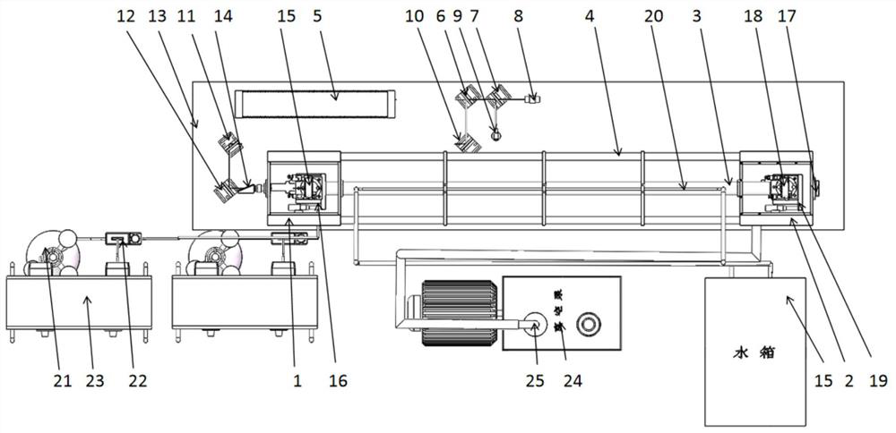
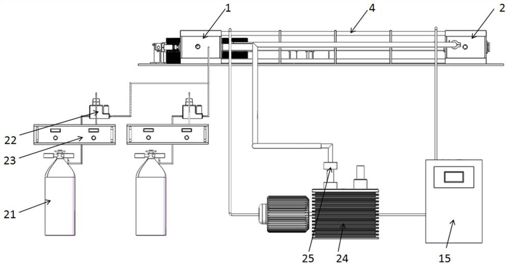
[0026] Such as Figure 1-4 As shown, a continuous gas-intake carbon dioxide pumped formic acid laser according to an embodiment of the present invention includes a far-infrared laser body, a carbon dioxide laser pumping optical path and supporting auxiliary equipment.

[0027] The main body of the far-infrared laser includes a vacuum chamber 1 at the pump end, a vacuum chamber 2 at the output end, a laser tube 3, and 4 Invars 4;

[0028] The carbo...


PUM


Abstract

The invention relates to a continuous air inlet type carbon dioxide pumping formic acid laser, which comprises a far infrared laser main body, a carbon dioxide laser pumping light path and matched auxiliary equipment, the far infrared laser main body comprises a pumping end vacuum cavity, an output end vacuum cavity, a laser tube and four pieces of invar steel; the carbon dioxide pumping light path comprises a carbon dioxide laser, a first light splitting sheet and a second light splitting sheet, the pumping end vacuum cavity comprises a Brewster window, an eccentric hole copper mirror, a mirror bracket and a stainless steel cavity, and all connecting parts of the cavity are kept sealed; the eccentric hole copper mirror is fixedly arranged in the pumping end vacuum cavity; the eccentric hole of the input end eccentric hole copper mirror is used for enabling the carbon dioxide light to resonate for multiple times, so that the pumping efficiency is improved, and the high-power carbon dioxide laser is prevented from returning to a pumping light path to damage an optical device; and the output end vacuum cavity comprises a poly (4-methylpentene-1) window and a central hole copper mirror arranged in the output end vacuum cavity.

Description

technical field [0001] The invention relates to the field of optical technology, in particular to a continuous gas-intake carbon dioxide pumped formic acid laser. Background technique [0002] THz waves refer to electromagnetic radiation with a frequency in the range of 0.1 to 10 THz (wavelength of 3000 to 30 microns). Its wavelength band is located in a fairly wide range of electromagnetic radiation between microwaves and infrared light. This section of the electromagnetic spectrum, including a part of the electromagnetic spectrum from the millimeter wave band (about 0.1THz) to the far-infrared region (about 25THz), is a very important spectrum in the study of condensed matter physics because it contains many factors that determine the properties of materials. important energy levels. Others, such as electron and phonon scattering and various tunneling mechanisms, mostly overlap with the THz wave region on the energy or time scale, and because the THz wave band contains t...

Claims


Application Information

Patent Timeline
IPC IPC(8): H01S3/0943H01S3/036H01S3/223
CPCH01S3/223H01S3/0943H01S3/036
Inventor 张际波魏学朝解家兴刘海庆揭银先王宏北
Owner HEFEI INSTITUTES OF PHYSICAL SCIENCE - CHINESE ACAD OF SCI
Learn More