Eureka AIR delivers breakthrough ideas for toughest innovation challenges, trusted by R&D personnel around the world.

Optical Fiber Phase Synchronization System Based on Optical Active Compensation

A technology of active compensation and phase synchronization, applied in optical fiber transmission, transmission system, electromagnetic wave transmission system, etc., can solve the problems of inability to transmit multiple frequency signals and time signals at the same time, limit the application range, etc., to improve the coherence of time-frequency transmission Effect

Active Publication Date: 2022-08-09
SHANGHAI INST OF OPTICS & FINE MECHANICS CHINESE ACAD OF SCI
View PDF4 Cites 0 Cited by
  • Summary
  • Abstract
  • Description
  • Claims
  • Application Information

AI Technical Summary

Problems solved by technology

[0005] Since the above technical solution adopts a passive compensation method, it can only achieve phase synchronization for specific frequency signals, and cannot transmit multiple frequency signals and time signals at the same time, which will limit its application scope to a certain extent

Method used


Image

  • Optical Fiber Phase Synchronization System Based on Optical Active Compensation
  • Optical Fiber Phase Synchronization System Based on Optical Active Compensation
  • Optical Fiber Phase Synchronization System Based on Optical Active Compensation

Examples


Embodiment Construction

[0031] The present invention will be further described below with reference to the embodiments and accompanying drawings, but the protection scope of the present invention should not be limited by this.

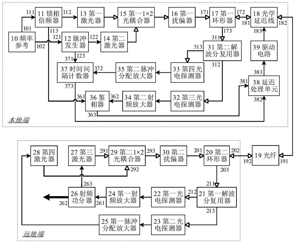
[0032] see figure 1 , figure 1This is a block diagram of the optical fiber phase synchronization system based on optical active compensation of the present invention. As can be seen from the figure, the optical fiber phase synchronization system based on optical active compensation of the present invention includes a frequency reference 10, a phase-locked frequency multiplier 11, a pulse generator 12, and a first laser. 13. The second laser 14, the first 1×2 optical coupler 15, the first polarizer 16, the first circulator 17, the optical delay line 18, the optical fiber 19, the second circulator 20, the first demultiplexer The device 21, the first photodetector 22, the second photodetector 23, the first radio frequency amplifier 24, the first pulse distribution amplifier 25,...


PUM


Abstract

The invention discloses an optical fiber phase synchronization system based on optical active compensation, comprising: a frequency reference, a phase-locked frequency multiplier, a pulse generator, a laser, a 1×2 optical coupler, a polarization scrambler, a circulator, and an optical delay line , optical fiber, demultiplexer, photodetector, radio frequency amplifier, pulse distribution amplifier, radio frequency power divider, phase detector, time interval counter, delay processing unit, drive circuit. The present invention can ensure that the frequency signal phases are consistent under operations such as shutdown and restart or optical fiber routing change, and realize phase synchronization, thereby improving the coherence of time-frequency transmission and meeting the requirements of coherent detection applications such as distributed radar arrays.

Description

technical field [0001] The invention relates to the field of optical fiber time-frequency transmission, in particular to an optical fiber phase synchronization system based on active optical compensation. The phases can be kept consistent, improving the coherence of time-frequency transmission, and can be used in fields such as coherent array detection. Background technique [0002] In recent years, with the rapid development of atomic frequency standards, time and frequency transfer technology has been continuously improved to meet the needs of advanced basic research and major research such as clock comparison, precise timing, precise measurement, navigation and positioning, radar networking and deep space exploration. application needs. Thanks to the advantages of low loss, anti-electromagnetic interference and high reliability of optical fiber links, optical fiber time-frequency transmission technology has developed rapidly, and its transmission accuracy is much higher ...

Claims


Application Information

Patent Timeline
Patent Type & Authority Patents(China)
IPC IPC(8): H04B10/61H04B10/25
CPCH04B10/6165
Inventor 吴瑞杨飞孙延光魏芳桂有珍蔡海文
Owner SHANGHAI INST OF OPTICS & FINE MECHANICS CHINESE ACAD OF SCI
Why Eureka
Eureka Blog
Learn More