Constant pressure control method and constant pressure adjusting device
A technology of constant pressure control and constant pressure regulation, applied in the direction of rolling mill control device, tension/pressure control, temperature control, etc., can solve difficult roll pressure control, roll gap and roll pressure can not be adjusted in time, hydraulic system momentum is large And other problems, to achieve high-precision rolling pressure control, ensure high-quality processing level, the effect of uniform effect
- Summary
- Abstract
- Description
- Claims
- Application Information
AI Technical Summary
Problems solved by technology
Method used
Image
Examples
Embodiment 1
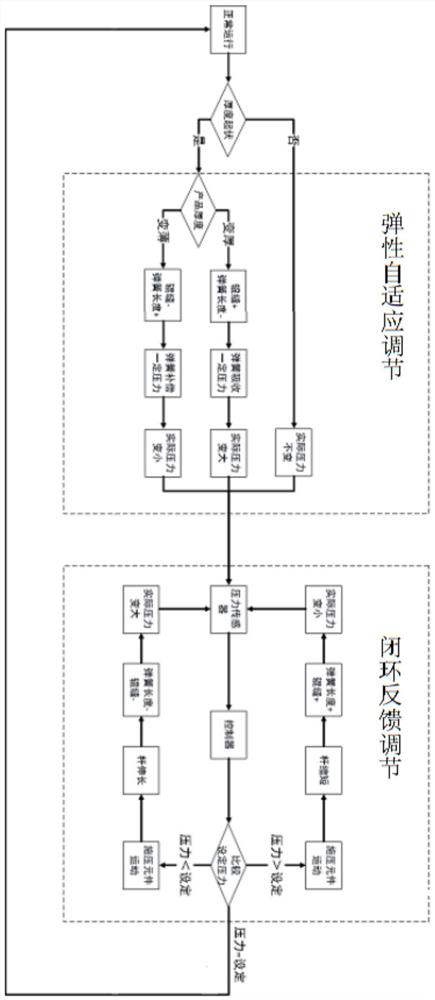
[0037] Embodiment 1: Specifically, in the elastic self-adaptive adjustment, the self-adjustment module perceives the change in the thickness of the product 1, and compensates or absorbs the change in the rolling pressure on the surface of the product 1 to realize the self-adaptive expansion and contraction adjustment. After the elastic self-adaptive adjustment, Variations in roll pressure have not been completely eliminated, so closed-loop feedback regulation is required.
[0038] In the closed-loop feedback adjustment, the sensor module 2 obtains the real-time rolling pressure, and the controller controls the pressure applying module 12 to adjust the rolling pressure to a set pressure value, and restore the pressure balance control.
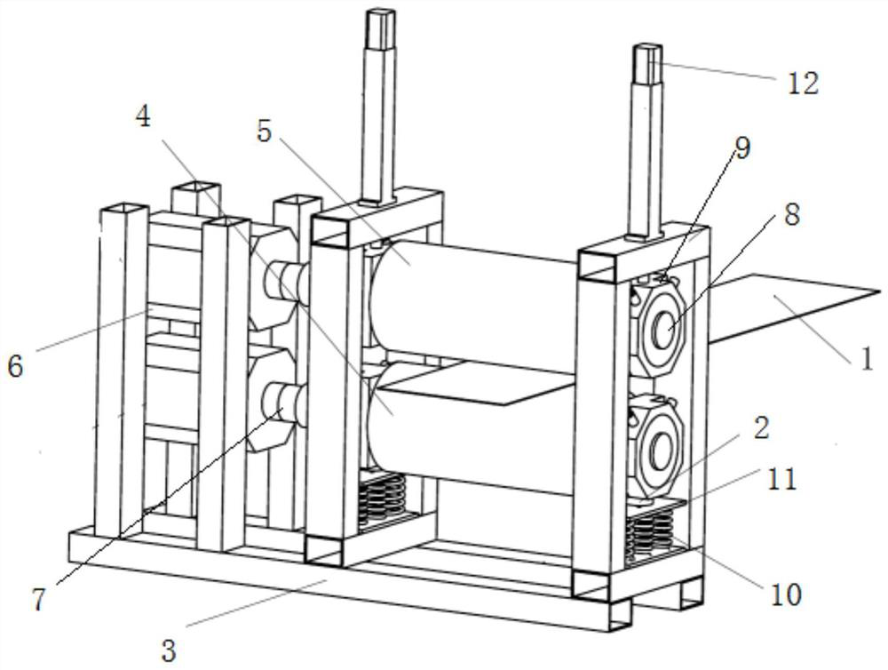
[0039] In this embodiment, it relates to a constant pressure regulating device using the above constant pressure control method for control and regulation, specifically, as figure 1 is a constant pressure regulator, and Figure 9 It is a consta...
Embodiment 2
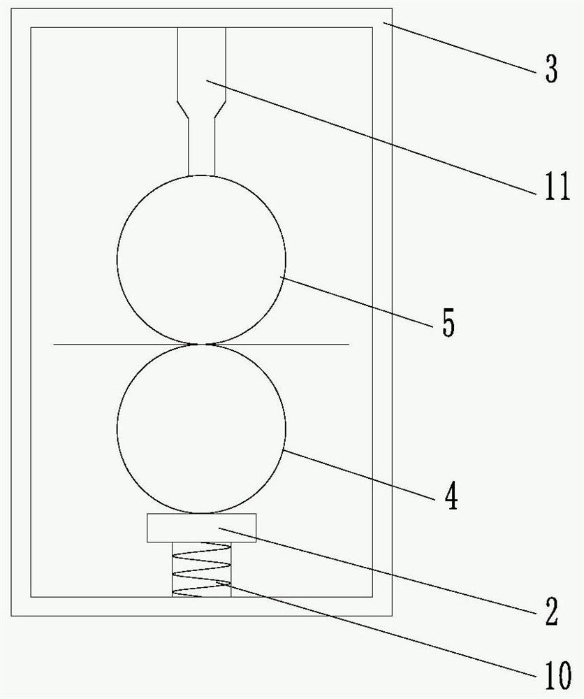
[0053] Embodiment two: refer to Figure 4 The difference between this embodiment and the first embodiment lies in the different installation positions of the sensor module 2, the spring 10 and the pressure applying device, specifically, the sensor module 2 is installed at the bottom of the frame 3, and the spring 10 is arranged between the sensor module 2 and the first between rolls 4.
Embodiment 3
[0054] Embodiment three: refer to Figure 5 , the sensor module 2 is installed between the first roller 4 and the frame 3 , and the spring 10 is arranged between the pressing module 11 and the top of the second roller 5 .
PUM
 Abstract
Description
Claims
Application Information
 - R&D
- Intellectual Property
- Life Sciences
- Materials
- Tech Scout
- Unparalleled Data Quality
- Higher Quality Content
- 60% Fewer Hallucinations
Browse by: Latest US Patents, China's latest patents, Technical Efficacy Thesaurus, Application Domain, Technology Topic, Popular Technical Reports.
© 2025 PatSnap. All rights reserved.Legal|Privacy policy|Modern Slavery Act Transparency Statement|Sitemap|About US| Contact US: help@patsnap.com


