
Control method of combustion system, combustion system and internal combustion engine

A combustion system and control method technology, applied in fuel injection control, electrical control, engine control, etc., can solve the problems of low air utilization, high fuel consumption of internal combustion engines, and low thermal efficiency, so as to promote rapid combustion, improve combustion efficiency, and improve The effect of burning speed

Active Publication Date: 2021-07-16
WEICHAI POWER CO LTD
View PDF8 Cites 3 Cited by
  • Summary
  • Abstract
  • Description
  • Claims
  • Application Information

AI Technical Summary

Problems solved by technology

However, the interval between the first injection and the second injection is too large in this way of dividing the main fuel injection into multiple times, resulting in almost zero superimposition effect of the entrainment effect space, low air utilization rate, low thermal efficiency, and high fuel consumption of the internal combustion engine.

Method used


Image

  • Control method of combustion system, combustion system and internal combustion engine
  • Control method of combustion system, combustion system and internal combustion engine
  • Control method of combustion system, combustion system and internal combustion engine

Examples


Embodiment 1

[0035] This embodiment provides an internal combustion engine. The internal combustion engine includes a combustion system. The combustion system mixes fuel and air and burns in a cylinder. The released heat can generate high-temperature and high-pressure gas in the cylinder. The gas expansion pushes the piston to do work, and then the mechanical work is output through the crank connecting rod mechanism or other mechanisms to drive the driven machinery to work.

[0036] The combustion system adopted by the internal combustion engine provided in this embodiment avoids excessive concentration of fuel at one time, and utilizes the spatial superposition of the entrainment effect generated between the first-stage main fuel injection and the second-stage main fuel injection, thereby improving the combustion efficiency and reducing the The fuel consumption is improved and the economy of the internal combustion engine is improved.

[0037] This embodiment also provides a combustion sy...

Embodiment 2

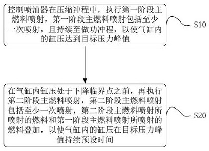
[0044] like figure 1 As shown, this embodiment provides a control method for a combustion system, and the control method for the combustion system includes:

[0045] S10. Control the injector to perform a first-stage main fuel injection during the compression stroke. The first-stage main fuel injection includes at least one injection and lasts until the power stroke, so that the cylinder pressure in the cylinder reaches the target pressure peak.

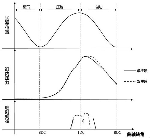
[0046] As a preferred embodiment of the control method of the combustion system, such as figure 2 As shown, the first stage main fuel injection includes a single injection that lasts from the piston compression stroke to the piston power stroke to establish a target pressure peak in the cylinder. It should be noted that in figure 2 Among them, single main injection refers to a single main fuel injection, dual main injection refers to the first stage main fuel injection and the second stage main fuel injection, TDC refers to the t...


PUM


Abstract

The invention discloses a control method of a combustion system, the combustion system and an internal combustion engine, and relates to the technical field of internal combustion engines. The combustion system comprises a piston, a fuel injector and an air cylinder, and the fuel injector injects main fuel into the air cylinder in sequence to drive the piston to do work in the main fuel injection stage. The control method of the combustion system comprises the steps that the fuel injector is controlled to execute first-stage main fuel injection in the compression stroke, and the first-stage main fuel injection comprises at least one time of injection which lasts to the acting stroke so that the cylinder pressure in the air cylinder can reach the target pressure peak value; and before the cylinder pressure in the air cylinder is at the descending critical point, second-stage main fuel injection is executed, the second-stage main fuel injection comprises at least one time of injection, and fuel injected by the second-stage main fuel injection and fuel injected by the first-stage main fuel injection are overlapped, so that the cylinder pressure in the air cylinder lasts for a preset time at the target pressure peak value. Accordingly, superposition of entrainment effects is promoted, the mixing area of fuel and air is increased, and the air utilization rate is increased.

Description

technical field [0001] The present invention relates to the technical field of internal combustion engines, in particular to a control method of a combustion system, a combustion system and an internal combustion engine. Background technique [0002] The traditional high-pressure common rail technology can achieve multiple injections, but its main injection form is the main fuel injection in the middle (more than 80% of the fuel is injected), and there are several small injections before and after (the injection volume accounts for about 10% to 20%) , its main purpose is to reduce combustion noise (pre-injection, that is, injection before main fuel injection) or to improve smoke emission and exhaust temperature thermal management (post-injection, that is, injection after main fuel injection). [0003] In order to further improve the performance of the internal combustion engine, it is proposed in the prior art to divide the main fuel injection in the multiple injections and ...

Claims


Application Information

Patent Timeline
IPC IPC(8): F02D41/38F02D41/40F02B77/08
CPCF02D41/38F02D41/402F02D41/3836F02B77/085F02D2041/389F02D35/023F02D41/403F02D41/405F02D2200/0602F02D41/2432F02D41/2467F02D2200/024
Inventor 谭旭光佟德辉周鹏刘晓鑫庞斌
Owner WEICHAI POWER CO LTD
Learn More