Electric reactor iron core structure, and manufacturing equipment and manufacturing method thereof

A technology of iron core structure and reactor, which is applied in the direction of inductance/transformer/magnet manufacturing, magnetic core manufacturing, transformer/inductor core, etc., which can solve the problems of reactor damage, high reactor heat, and poor heat dissipation. To achieve the effect of improving the service life and improving the heat dissipation effect

Active Publication Date: 2021-07-16
上海波亮电器制造有限公司
View PDF12 Cites 2 Cited by
  • Summary
  • Abstract
  • Description
  • Claims
  • Application Information

AI Technical Summary

Problems solved by technology

[0004] In view of the above-mentioned related technologies, the inventor believes that there are the following defects: the structure of the reactor is a fixed plate up and down, two magnetic cores are fixed in the fixed plate, and the outer side of the magnetic core is wound with wires. In actual use, due to the magnetic core It is tightly wrapped and wound, and the internal heat dissipation is poor. Although the reactor shell is provided with vents, it can only dissipate the heat from the outer surface of the reactor, which leads to high heat of the reactor. It is easy to cause damage to the reactor

Method used


Image

  • Electric reactor iron core structure, and manufacturing equipment and manufacturing method thereof
  • Electric reactor iron core structure, and manufacturing equipment and manufacturing method thereof
  • Electric reactor iron core structure, and manufacturing equipment and manufacturing method thereof

Examples


Embodiment Construction

[0047] The following is attached Figure 1-9 The application is described in further detail.

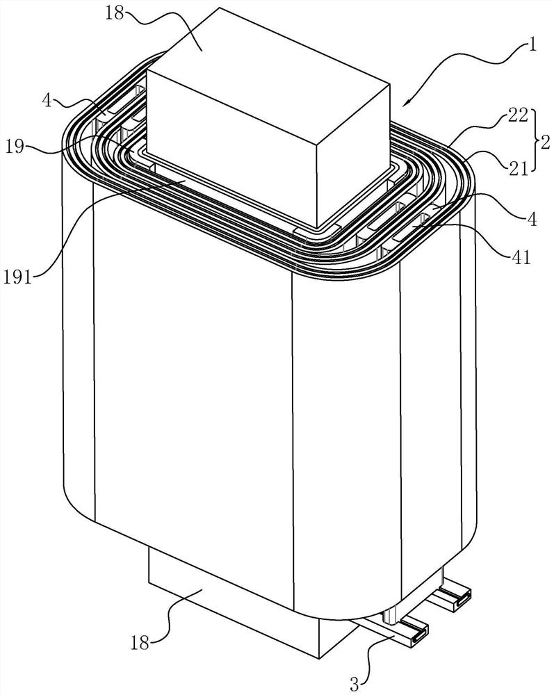
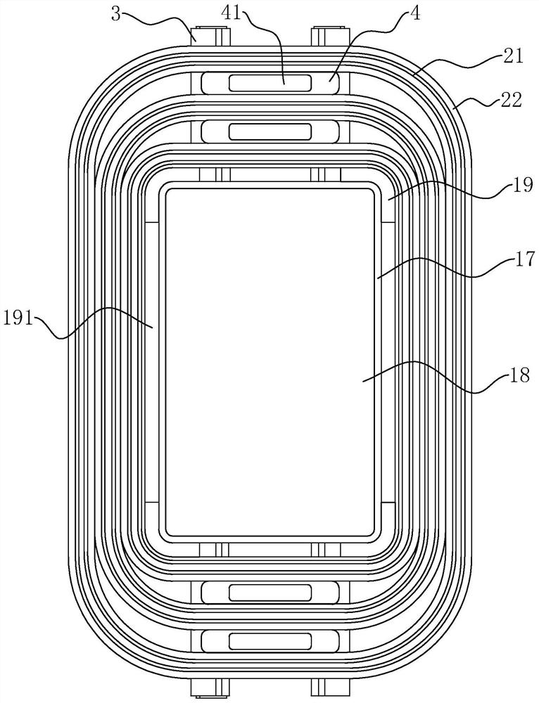
[0048] The embodiment of this application discloses a reactor core structure, refer to figure 1 , including a magnetic core cake 1 and a winding 2 wound on the magnetic core cake 1 , the wire group includes insulating paper layers 21 and aluminum foil tape layers 22 stacked alternately.

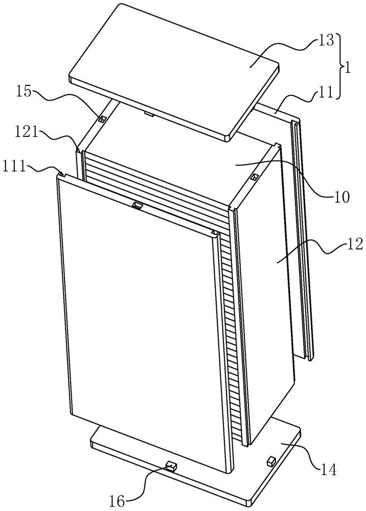
[0049] refer to figure 1 , figure 2 The magnetic core cake 1 includes two first side plates 11 arranged parallel to each other, two second side plates 12 arranged parallel to each other, an upper sealing plate 13 and a lower sealing plate 14, the first side plate 11, the second side plate 12. The upper sealing plate 13 and the lower sealing plate 14 form a cube, and the magnetic core cake 1 is provided with a plurality of chips 10 arranged horizontally and stacked on top of each other. The chip 10 is parallel to the upper sealing plate 13 and the lower sealing plate 14 , and the chip 10 is perp...


PUM


Abstract

The invention relates to an electric reactor iron core structure. The structure comprises a magnetic core cake and a winding wound on the magnetic core cake, the winding comprises an insulation paper layer and an aluminum foil tape layer which are mutually staggered and stacked, the outer side wall of the magnetic core cake is coated with an epoxy resin layer, division bars are fixed to the four vertex angles of the magnetic core cake in a protruding mode, and the division bars are fixedly connected to the epoxy resin layer. The length direction of the division bars is parallel to the length direction of the magnetic core cake, the winding is wound on the division bar, and a first heat dissipation air channel is formed between the inner wall of the winding and the outer wall of the magnetic core cake; and mounting plates are arranged on the two opposite outer side walls of the magnetic core cake in a protruding mode, a plurality of partition plates are arranged on the mounting plates, the length direction of the partition plates is parallel to the length direction of the magnetic core cake, winding cavities allowing windings to penetrate through and be wound are formed between the partition plates and the partition strips and between every two adjacent partition plates on the same mounting plate, and second heat dissipation air channels are formed in the end faces of the partition plates in a penetrating mode. The structure has the advantage that the heat dissipation effect of the reactor is improved.

Description

technical field [0001] The present application relates to the technical field of reactor production, in particular to a reactor core structure, manufacturing equipment and a manufacturing method thereof. Background technique [0002] A reactor is also called an inductor. When a conductor is energized, it will generate a magnetic field in a certain space it occupies, so all electric conductors that can carry current have inductance in the general sense. According to the structure and cooling medium: divided into hollow type, iron core type, dry type, oil-immersed type, etc. [0003] Due to the wide application of reactors in power electronic components, the efficiency and power loss of reactors in various environments are also concerned by the industry, especially in high-frequency environments. The requirements are more stringent. [0004] In view of the above-mentioned related technologies, the inventor believes that there are the following defects: the structure of the r...

Claims


Application Information

Patent Timeline
Patent Type & Authority Applications(China)
IPC IPC(8): H01F27/24H01F27/08H01F27/30H01F41/02H01F41/06
CPCH01F27/24H01F27/08H01F27/306H01F27/085H01F41/0206H01F41/06
Inventor 李华春
Owner 上海波亮电器制造有限公司
Why Eureka
Try Eureka