Resistance spot welding method for welding plate group

A technology for resistance spot welding and welding of plates, applied in resistance welding equipment, welding equipment, metal processing equipment, etc., can solve the problems of short electrode life and LME cracks on the surface of welded joints of coated steel plates, so as to improve electrode life and avoid LME. Cracks, the effect of saving welding time

Active Publication Date: 2021-07-20
SHOUGANG CORPORATION
View PDF9 Cites 3 Cited by
  • Summary
  • Abstract
  • Description
  • Claims
  • Application Information

AI Technical Summary

Problems solved by technology

[0005] The embodiment of the present application provides a resistance spot welding method for welding plate groups, which solves the technical problems of short life of electrodes and LME cracks on the surface of solder joints of coated steel plates in the prior art

Method used


Image

  • Resistance spot welding method for welding plate group
  • Resistance spot welding method for welding plate group
  • Resistance spot welding method for welding plate group

Examples


Embodiment 1

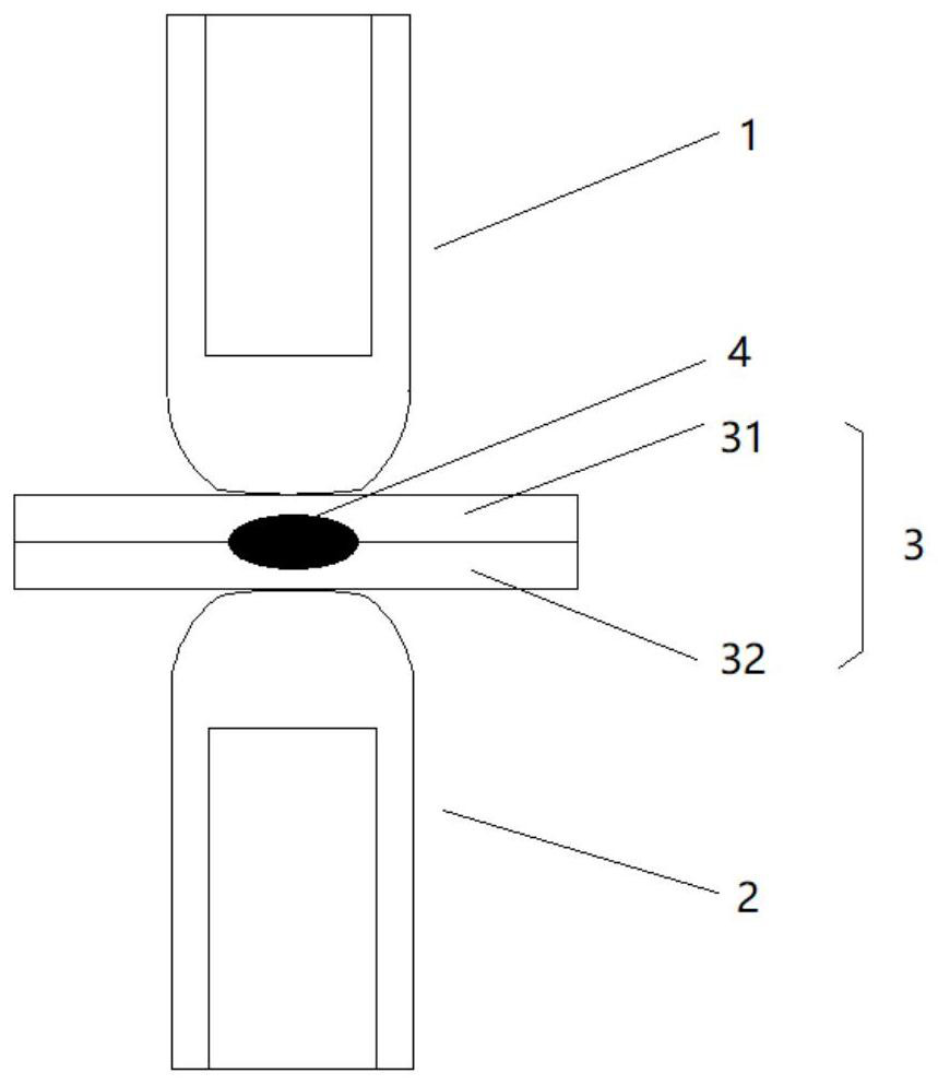
[0078] The top test plate 31 is 1.4mm thick Trip1000, and there are 50 g / m on both sides. 2 The Zn coating, the underlying test plate 32 is 1.4mm thick Trip1000, both sides have 50 g / m 2 The Zn plating layer, by the top test plate 31, the underlying test plate 32 constitutes the welding plate group 3.

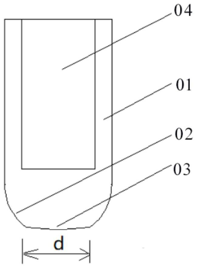
[0079] In response to the characteristics of the weld plate group 3, the upper electrode 1, the lower electrode 2 is the same, the working surface 03 diameter D = 8 mm, the radius of curvature R = 50 mm, the cylindrical region 01 diameter is 20mm, the cooling tank 04 has cooling water, the flow rate is 4L / min.

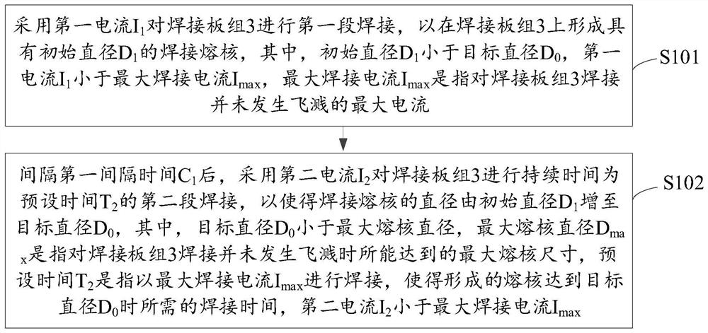
[0080] In electrode pressure N 0 = 4KN, welding time t 0 Under the conditions of 560ms, the splash current I when I have splash occurred. splash = 9.9kA, maximum welding current I max = 9.7kA, at this time, the corresponding melted maximum melted diameter D max = 7.05mm;

[0081] In electrode pressure N 0 = 4KN, maximum welding current I max Under 9.7kA, determine the...

Embodiment 2

[0092] The top test plate 31 is 1.4mm thick Trip1000, and there are 50 g / m on both sides. 2 Zn plating; underlying test plate 32 is 1.4mm thick DP600, 50g / m on both sides 2 Zn plating; from the top test plate 31, the underlying test plate 32 constitutes the weld plate group 3.

[0093] In response to the characteristics of the weld plate group 3, the upper electrode 1, the working surface 03 diameter D = 8 mm of the lower electrode 2 is selected, and the cylindrical region 01 is 20 mm, and the cooling water 04 is cooled, and the flow rate is 4 l / min.

[0094] Since the Trip1000 strength is high and contains residual austenite tissue, the DP600 intensity is low and no residual austenite tissue, so the TRIP1000 welding LME is highly sensitive. Select the upper electrode 1 working surface 03 curvature radius R = 100 mm in contact with Trip1000, and the lower electrode 2 working surface 03 curvature radius r = 50 mm in contact with DP600, the upper electrode 1 working surface 03...


PUM


Abstract

The invention discloses a resistance spot welding method for a coated steel plate, and is applied to welding of a resistance spot welding device on a welding plate group. The method comprises the following steps that first-section welding is conducted on the welding plate group by adopting a first current to form a welding nugget with an initial diameter on the welding plate group, the first current being smaller than a maximum welding current; and after first interval time, a second current is adopted for conducting second-section welding with a duration being preset time on the welding plate group, so that a diameter of the welding nugget is increased to a target diameter, the target diameter being smaller than a maximum nugget diameter, the preset time being welding time required when welding is conducted by using the maximum welding current so as to enable the formed nugget to reach the target diameter, and the second current being smaller than the maximum welding current. According to the method, a welding process has a lower welding temperature and shorter high-temperature retention time, and the technical problems that in the prior art, the service life of an electrode is short, and LME cracks exist on the surface of a welding spot of the coated steel plate are solved.

Description

Technical field [0001] The present invention relates to the technical field of resistance spot welding, and more particularly to a resistance spot welding method of a weld plate group. Background technique [0002] Resistance spot welding is to fit the solder into a lap joint, and press the upper and lower electrodes (usually, the upper and lower electrodes are identical), and the material is used to melt the material metal to form a solder joint resistance welding. method. Spot welding is mainly used for thin plate welding, and has a wide range of applications in industries such as automobiles, home appliances. [0003] With the increasing corrosion resistance of the modern manufacturing, the application range of galvanized plates, galvanized iron alloy steel plates, galvanized aluminum magnesium steel plates and other welding plates are gradually expanded. The main problems faced by the weld plate resistance point welding include: [0004] 1) Short electrode life; 2) The surfac...

Claims


Application Information

Patent Timeline
Patent Type & Authority Applications(China)
IPC IPC(8): B23K11/11B23K11/36
CPCB23K11/11B23K11/115B23K11/36
Inventor 张永强伊日贵付参王鹏博鞠建斌
Owner SHOUGANG CORPORATION
Why Eureka
Try Eureka