
A passive containment heat export system with diversion structure

A passive containment and heat export technology, applied in the field of passive safety systems of nuclear reactors, can solve the problems of insufficient attention, reduce the heat transfer efficiency of heat exchangers, affect the condensation heat transfer effect, etc., and achieve the improvement of gas flow conditions , ensuring safety, reducing the effect of weakening

Active Publication Date: 2022-02-18
CHINA NUCLEAR POWER ENG CO LTD
View PDF13 Cites 0 Cited by
  • Summary
  • Abstract
  • Description
  • Claims
  • Application Information

AI Technical Summary

Problems solved by technology

The existence of non-condensable gas will significantly affect the effect of condensation heat transfer and reduce the heat transfer efficiency of the heat exchanger
In existing inventions, the addition of flow guide structures to improve the gas flow conditions near the PCS internal heat exchanger and the distribution of non-condensable gases has not received enough attention, such as the patent application number CN201610801851.5 "A new type of passive Containment Energy Control System” and the patent application number CN201810662009.7 “A Closed Passive Containment Cooling System for Floating Nuclear Power Plants” both focus on strengthening the heat exchanger structure or improving the heat exchange environment to strengthen the heat exchanger. The heat transfer capacity of the system is improved, but the heat transfer is not enhanced by improving the flow field near the internal heat exchanger and the distribution of non-condensable gases

Method used


Image

  • A passive containment heat export system with diversion structure
  • A passive containment heat export system with diversion structure
  • A passive containment heat export system with diversion structure

Examples


Embodiment 1

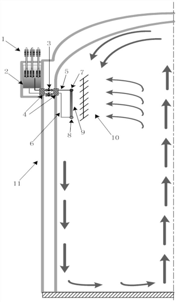
[0030] Such as figure 1 As shown, a passive containment heat export system with a diversion structure according to the present invention is arranged on the inside and outside of the containment 11, including the inner part of the containment and the outer part of the containment; the inner part of the containment Located on the upper part of the inner side wall of the containment, the main body includes an internal heat exchanger and a flow guide structure; the outer part of the containment is located above the outer side wall of the containment, and the main structure includes an external cooling water tank and a steam-water separator; the inner part of the containment It is connected with the outer part of the containment through pipelines and valves.

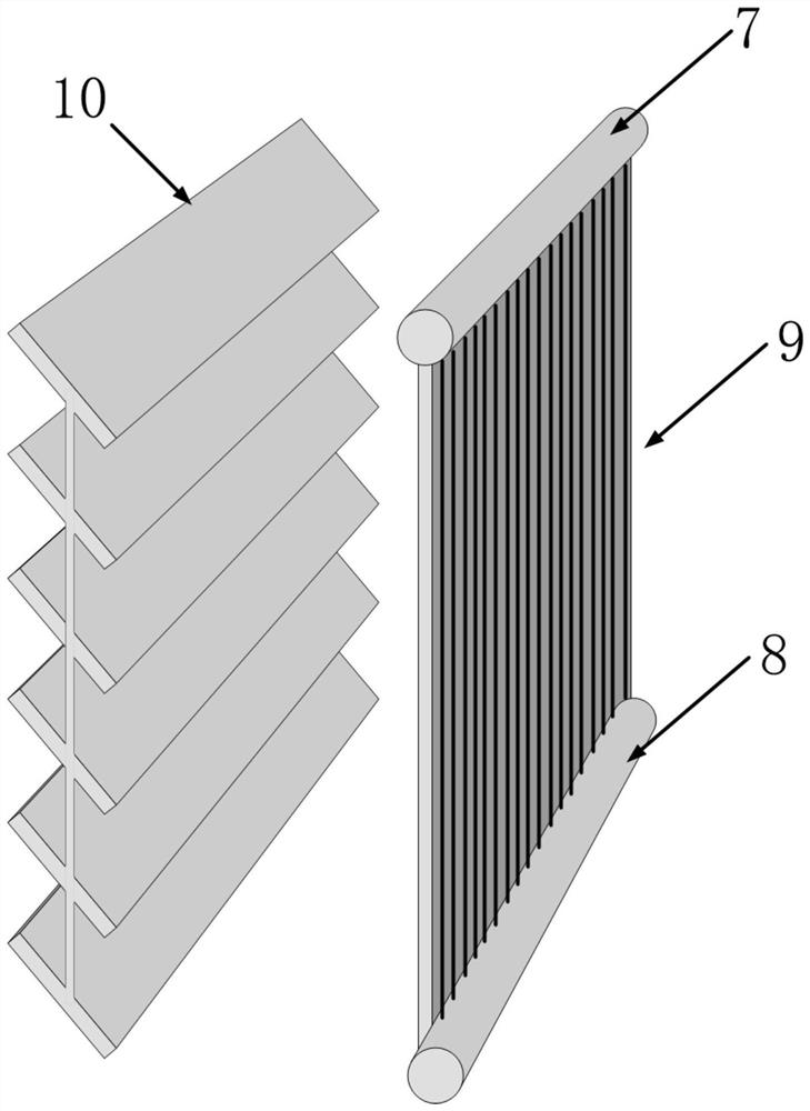
[0031] The flow guide structure of the inner part of the containment is arranged parallel to the internal heat exchanger, which is a louver-type flow guide structure 10, and the blades are made of rectangular stainless steel ...

Embodiment 2

[0037] Such as figure 1 As shown, a passive containment heat export system with a diversion structure according to the present invention is arranged on the inside and outside of the containment 11, including the inner part of the containment, the outer part of the containment, and the part connected to the inner part of the containment , pipelines on the outer part of the containment;

[0038] The outer part of the containment vessel includes a heat pipe 1 and an external cooling water tank 2; wherein, the external cooling water tank 2 is arranged above the outer side wall of the containment vessel, and the heat pipe 1 is arranged in the external cooling water tank 2 to strengthen the cooling of the external cooling water tank 2 ;

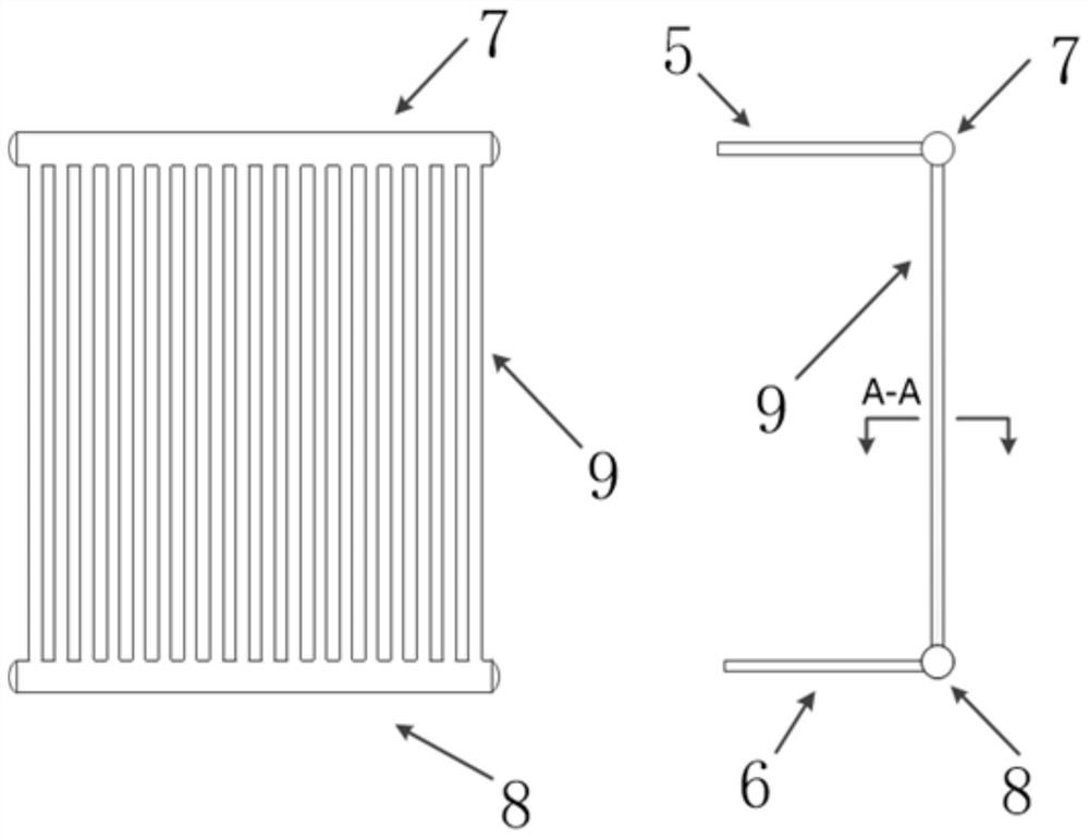
[0039] The inner part of the containment includes a heat exchange tube 9, an upper header 7 of the heat exchanger, a lower header 8 of the heat exchanger, and a flow guide structure 10; wherein, the upper end of the heat exchange tube 9 is connect...

Embodiment 3

[0047] Such as figure 1 As shown, a reactor with the passive containment heat extraction system described in Embodiment 1 or Embodiment 2. The passive containment cooling system includes a containment inner part and a containment outer part. The inner part of the containment vessel is located inside the containment vessel, and the main body includes an internal heat exchanger and a flow guide structure; the outer part of the containment vessel is located above the outer side wall of the containment vessel, and the main structure includes an external cooling water tank and a steam-water separator. The inner part of the containment vessel is connected with the outer part through pipelines and valves.

[0048] The outer part of the containment includes a heat pipe 1, an external cooling water tank 2, an inlet and outlet isolation valve 3, a penetration piece 4, an ascending pipeline 5 and a descending pipeline 6; the external cooling water tank 2 is arranged at a high place outs...


PUM


Abstract

The invention relates to the field of passive safety systems for nuclear reactors, in particular to a passive containment heat export system with a flow guiding structure. The system is arranged on the inner and outer sides of the containment, including the inner part of the containment and the outer part of the containment; the inner part of the containment is located on the upper part of the inner side wall of the containment, and the main body includes an internal heat exchanger and a flow guiding structure; the said The outer part of the containment is located above the outer sidewall of the containment, and the main structure includes an external cooling water tank and a steam-water separator; the inner part of the containment and the outer part of the containment are connected by pipelines and valves. According to the characteristics of gas flow distribution in the containment under accident conditions, the invention effectively improves the gas flow near the internal heat exchanger of the PCS by arranging a diversion structure near the heat exchanger, and reduces the accumulation of non-condensable gas near the internal heat exchanger. The deteriorating effect of condensation heat exchange, and the heat exchange efficiency of PCS is improved.

Description

technical field [0001] The invention relates to the field of nuclear reactor passive safety systems, in particular to a passive containment heat derivation system with a diversion structure. Background technique [0002] Since nuclear power generation was developed and utilized in the middle of the last century, it has continuously provided mankind with efficient and clean energy. However, due to the unique physical properties of nuclear materials and the huge impact of nuclear accidents in history on society and the environment, the safety of nuclear power has received great attention. Combined with nuclear power operation experience and technological development, the concept of passive safety systems has been introduced into the design process of many third-generation nuclear power plants. The passive safety system can use natural phenomena such as density difference and gravity difference to ensure the safety of the reactor without external power support. my country's th...

Claims


Application Information

Patent Timeline
Patent Type & Authority Patents(China)
IPC IPC(8): G21C15/12G21C15/14G21C15/18
CPCG21C15/12G21C15/14G21C15/18Y02E30/30
Inventor 邢继李伟于勇吴宇翔马佳鹏谌登华高力刘倩雯王诚诚
Owner CHINA NUCLEAR POWER ENG CO LTD
Learn More