
Industrial tail gas treatment multi-cycle adsorption tower

A technology of industrial tail gas and adsorption tower, applied in the direction of gas treatment, dispersed particle separation, membrane technology, etc., can solve problems such as fire hazards, air pollution, ammonia escape, etc., to improve flue gas treatment capacity, increase contact time, reduce The effect of footprint

Pending Publication Date: 2021-07-23
GUODIAN ENVIRONMENTAL PROTECTION RES INST CO LTD
View PDF0 Cites 3 Cited by
  • Summary
  • Abstract
  • Description
  • Claims
  • Application Information

AI Technical Summary

Problems solved by technology

In this technology, the adsorption tower is the core equipment for removing pollutants. Due to the influence of structural design and flue gas flow characteristics of the existing adsorption tower, the distribution of flue gas in the tower is uneven, and local active coke does not participate in flue gas purification or has a low degree of participation. , the active coke cannot be effectively used and the loss increases. In addition, the local part of the tower is prone to rapid temperature rise. A large amount of protective gas nitrogen needs to be introduced into the tower and cannot quickly act on high-temperature parts, which will cause fire hazards.
The denitrification of the adsorption tower is the first-level ammonia injection or the second-level ammonia injection. On the one hand, the denitrification rate of this process is not high, and there is still a certain amount of nitrogen oxides in the flue gas after purification. On the other hand, excessive injection of ammonia gas will cause ammonia to escape, which will cause air pollution

Method used


Image

  • Industrial tail gas treatment multi-cycle adsorption tower
  • Industrial tail gas treatment multi-cycle adsorption tower
  • Industrial tail gas treatment multi-cycle adsorption tower

Examples


Embodiment

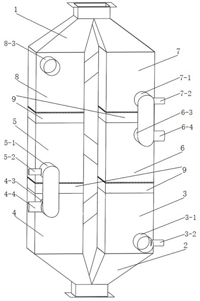
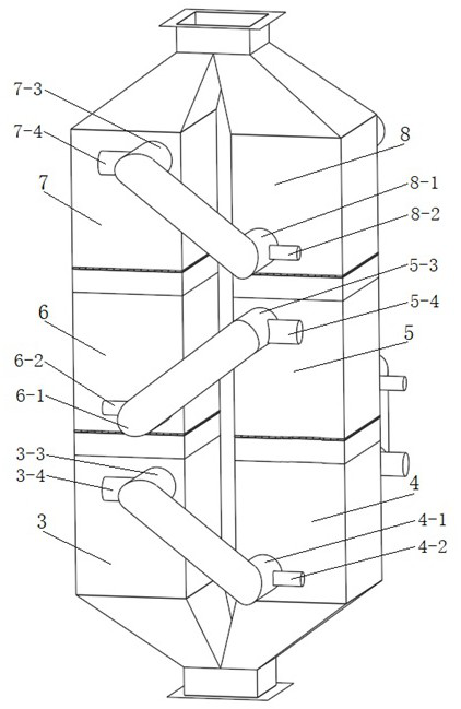
[0029] Such as figure 1 and figure 2 As shown, the industrial tail gas treatment multi-cycle adsorption tower of the present invention includes several tower bodies arranged side by side. In this embodiment, there are two tower bodies, and each tower body is sequentially provided with active coke feeding sections 1. The flue gas purification section and the active coke discharge section 2; there are three flue gas purification sections in each tower body, and the three flue gas purification sections are set up and down, and a transitional sealing section is provided between adjacent flue gas purification sections 9.

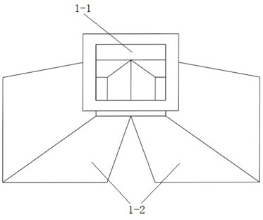
[0030] Such as image 3 As shown, the active coke feed section 1 is composed of the feed straight section 1-1 and the feed cone section 1-2, and the upper and lower ends of the feed cone section 1-2 are respectively connected with the feed straight section 1-1 and a flue gas The purification section, and the cross-section gradually increases from top to botto...


PUM


Abstract

The invention relates to an industrial tail gas treatment multi-cycle adsorption tower which comprises a plurality of tower bodies arranged side by side, each tower body comprises an active coke feeding section, at least two flue gas purification sections and an active coke discharging section which are sequentially arranged from top to bottom, the flue gas purification sections in each tower body are the same in number and at least two, and a transition sealing section is arranged between two adjacent flue gas purification sections on the same tower body; a gas inlet pipe and a gas outlet pipe are respectively arranged at the lower part and the upper part of each flue gas purification section; the gas outlet pipe of one flue gas purification section is connected with the gas inlet pipe of another corresponding flue gas purification section at the same height of other tower bodies or the gas inlet pipe of the adjacent flue gas purification section above the same tower body; and the gas inlet pipe of the flue gas purification section at the bottom is the gas inlet pipe of the adsorption tower, and the gas outlet pipe of the flue gas purification section at the top is the gas outlet pipe of the adsorption tower. The adsorption tower improves the utilization rate of active coke in the adsorption tower.

Description

technical field [0001] The invention relates to a multi-cycle adsorption tower for industrial tail gas treatment, which belongs to the technical field of industrial tail gas purification. Background technique [0002] As a dry flue gas treatment technology, the activated coke industrial tail gas integrated purification process can simultaneously remove sulfur dioxide, nitrogen oxides, dioxins, heavy metals and other pollutants in the flue gas, and has desulfurization by-products that can be recycled Utilization, does not consume water resources, does not cause secondary pollution such as waste water and waste gas, etc. In this technology, the adsorption tower is the core equipment for removing pollutants. Due to the influence of structural design and flue gas flow characteristics of the existing adsorption tower, the distribution of flue gas in the tower is uneven, and local active coke does not participate in flue gas purification or has a low degree of participation. , th...

Claims


Application Information

Patent Timeline
Patent Type & Authority Applications(China)
IPC IPC(8): B01D53/06
CPCB01D53/06B01D2258/0283
Inventor 谷建功许芸王亮樊腾飞程文煜孟春强邱祥民刘涛邢德山
Owner GUODIAN ENVIRONMENTAL PROTECTION RES INST CO LTD
Learn More