Rapid sintering preparation method of infrared transparent ceramic

A technology for transparent ceramics and rapid sintering, applied in the field of transparent ceramic material preparation, can solve the problems of shortening the heating time and reducing the sintering activity of powders, achieves grain refinement, low production cost, and inhibits abnormal grain size growth Effect

Pending Publication Date: 2021-07-27
SHANGHAI INST OF OPTICS & FINE MECHANICS CHINESE ACAD OF SCI
View PDF10 Cites 1 Cited by
  • Summary
  • Abstract
  • Description
  • Claims
  • Application Information

AI Technical Summary

Problems solved by technology

[0006] The purpose of the present invention is to provide a rapid sintering preparation method for infrared transparent ceramics, which overcomes the defects of the existing ceramic sintering preparation process in terms of simultaneous densification and grain refinement, and high-quality and large-scale preparation.
The key point is to push the sample directly from the low temperature zone to the high temperature zone for sintering, so that it can

Method used


Image

  • Rapid sintering preparation method of infrared transparent ceramic
  • Rapid sintering preparation method of infrared transparent ceramic
  • Rapid sintering preparation method of infrared transparent ceramic

Examples


Example Embodiment

[0033] Example 1

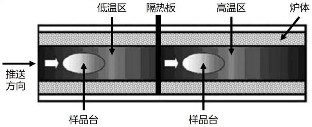
[0034] Use Y 2 O 3 -MGO composite nanoparticles, weigh 20g powder The mold pressurization is 3 MPa dry pressure as a ceramic blank, and the blank is pressured for 280 MPa, and the pressure retaining time is 3 min is static. The high temperature zone is hit by the high temperature zone of the muffle to 1600 ° C to be used, and the ceramics On the low temperature zone platform of the muffle furnace, the temperature is increased to 1200 ° C for 200 min at 1 ° C / min; lift the heat insulating plate of the high temperature zone and the low temperature zone to quickly push the sample table and the sample to the high temperature zone, carry out 10 min After the insulation is sintered, after the sintering is completed, the furnace is cooled, and the high-density nano-grain ceramic sample is obtained; then perform two high-precision mirror polishing processing, which has a thickness of 3.0mm. 2 O 3 -MGO nano-phase ceramic product.
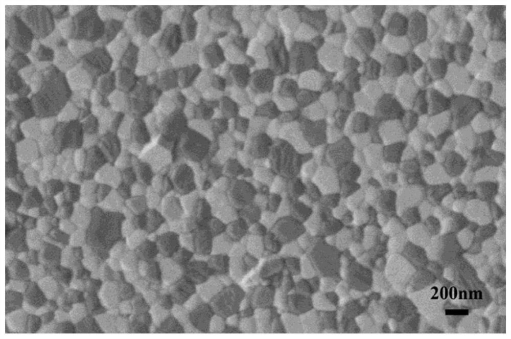
[0035] figure 2 Yes made in Example...

Example Embodiment

[0037] Example 2

[0038] Using commercial ZRO 2 Nanofin, weigh 80g powder The mold pressurization is 30 MPa to ceramic billet, and the blank is pressured for 180 MPa, and the pressure pressure time is 20 min, and the high temperature zone is hit by the high temperature zone of the muffle to 1200 ° C to be used, and the ceramics On the sample table of the Maververter Holtaicone, the temperature is warmed to 800 ° C for 10 min at a temperature of 5 ° C / min; lift the heat insulating plate of the high temperature zone and the low temperature zone to quickly push the sample table and the sample to the high temperature zone. 200min insulation sintering, after the end of sintering, the furnace is cooled, produce high-density nano-grain ceramic samples; then carry out double-sided high-precision mirror polishing, obtain ZRO having a thickness of 3.0 mm 2 Ceramic product.

[0039] Figure 4 Zro made in Example 2 2 Ceramic SEM topography; It can be seen from the figure that the average ...


PUM

PropertyMeasurementUnit
Average grain sizeaaaaaaaaaa

Abstract

The invention relates to a rapid sintering preparation method of infrared transparent ceramic. The method comprises the following steps: firstly, pressing nano powder to form a ceramic biscuit, putting the biscuit into a low-temperature area of a double-temperature-area muffle furnace, heating to a preset temperature, preserving heat, eliminating internal stress caused by a sample in a forming process, and reducing moisture absorbed by the sample in a preparation process; and then pushing the sample to a high-temperature area, carrying out heat-preservation sintering, and cooling along with the furnace after sintering is finished, so as to prepare the high-density nano-crystalline-grain ceramic. The relative density of the obtained ceramic sample is 95%-100%, the grain size is smaller than 250 nm, and the ceramic sample has good optical performance and mechanical performance.

Description

Technical field [0001] The present invention relates to a rapid sintering preparation method of infrared transparent ceramic, belonging to the field of transparent ceramic material. Background technique [0002] Mature ceramic molding and sintering technologies have thousands of years, and the pottery and porcelain prepared by different sintering process technologies have met the different needs of people's production and life. In recent years, high-performance ceramics of different sintering process techniques have been used to obtain better optical, mechanics, thermophysics, electrical, magnetics, and meet more practical applications, such as environmental protection. , Security, military, national defense, etc., is the pursuit of relevant researchers. According to the Hall-Petch relationship, the smaller the grain size of the ceramic, the higher the hardness and strength. In the nanocrystalline ceramic, the smaller the grain size, the higher the relative caused density, the sm...

Claims


Application Information

Patent Timeline
IPC IPC(8): C04B35/505C04B35/053C04B35/486C04B35/115C04B35/64
CPCC04B35/505C04B35/053C04B35/486C04B35/115C04B35/64C04B2235/5454C04B2235/785C04B2235/96C04B2235/9653C04B2235/6562C04B2235/6567
Inventor 范金太沈宗云钱凯臣张龙谢俊喜冯涛姜本学冯明辉陈柏键张露露范翔龙
Owner SHANGHAI INST OF OPTICS & FINE MECHANICS CHINESE ACAD OF SCI
Why Eureka
Try Eureka