Implantable catheter, use method and preparation method thereof

An implantable catheter technology, which is applied in the direction of catheters, cardiac catheters, balloon catheters, etc., can solve the problems of patient infection, poor pressure measurement accuracy, easy to fall off heparin coating, etc., and achieve the effect of reducing the diameter and simplifying the structure

Inactive Publication Date: 2021-07-30
HANGZHOU WEIMING XINKE TECH CO LTD +1
View PDF3 Cites 0 Cited by
  • Summary
  • Abstract
  • Description
  • Claims
  • Application Information

AI Technical Summary

Problems solved by technology

This method not only has poor pressure measurement accuracy, but also easily leads to infection of patients.
In addition, the current traditional catheters and their coatings mostly use PVC+heparin coating, but the heparin coating is prone to fall off and then fails during use

Method used


Image

  • Implantable catheter, use method and preparation method thereof
  • Implantable catheter, use method and preparation method thereof
  • Implantable catheter, use method and preparation method thereof

Examples


Embodiment 1

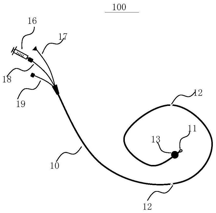
[0080] This example involves a method for installing a single first pressure sensor with a size not exceeding 1mm×1mm×0.5mm on the pipe body, which specifically includes the following steps:

[0081] In the first step, the inflatable cavity at the distal end of the tube is sealed, and the sealing distance does not exceed 3cm;

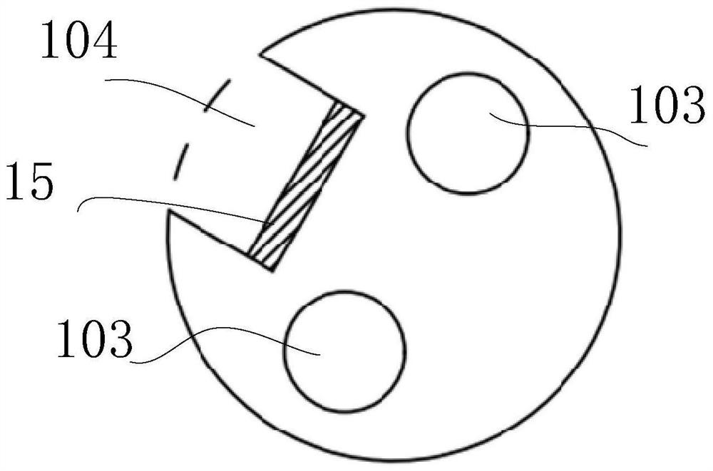
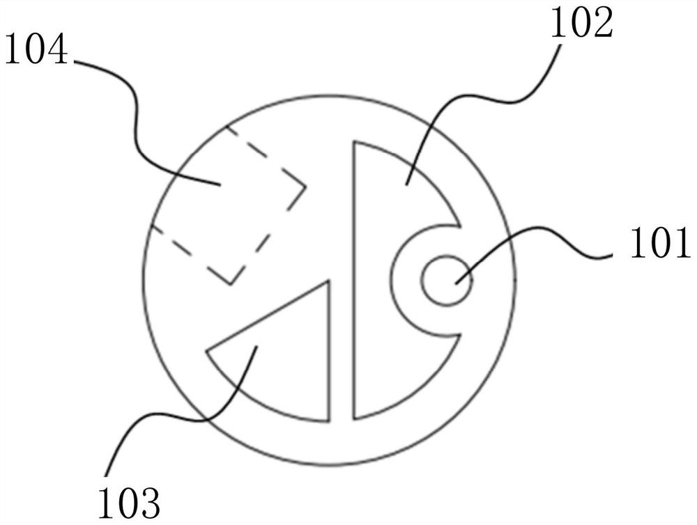
[0082] In the second step, the Figures 8a-9d The first base shown in is connected to the far end of the tube body by means of AB glue bonding, and a hole is opened on the side wall of the tube body to reserve a through channel with the guide wire lumen;

[0083] The third step is to operate under a microscope, and use photosensitive UV glue to glue the first pressure sensor on the first base at the far end, and guide the lead wires into the wire lumen through the holes on the side wall;

[0084] The fourth step is to use a silicone sleeve to protect the position where the sensor is installed on the tube body with protective adhesive to ensure airtight...

Embodiment 2

[0090]This embodiment relates to a method for installing the first pressure sensor and the second pressure sensor with a size not exceeding 1mm×1mm×0.5mm on the pipe body, that is, installing the first pressure sensor at the far end of the pipe body, and installing the second pressure sensor on the side wall of the pipe body. Two second pressure sensors, for a total of three sensors. Specifically include the following steps:

[0091] In the first step, the inflatable cavity at the distal end of the tube is sealed, and the sealing distance does not exceed 3 cm;

[0092] In the second step, the Figures 8a-9d The first base described in is connected to the far end of the tube body by AB glue bonding; and a hole is opened on the side wall of the tube body to reserve a through channel with the guide wire lumen;

[0093] The third step is to operate under a microscope, use photosensitive UV glue to glue the first pressure sensor on the first base, and guide the lead wires into th...

Embodiment 3

[0101] This embodiment relates to a method for installing a first pressure sensor with a size not exceeding 2mm×2mm×1mm on a pipe body, which specifically includes the following steps:

[0102] In the first step, the inflatable cavity at the distal end of the tube is sealed, and the sealing distance does not exceed 3cm;

[0103] In the second step, the Figures 8a-9d The first base described in is connected to the far end of the tube body by AB glue bonding; and a hole is opened on the side wall of the tube body to reserve a through channel with the guide wire lumen;

[0104] The third step is to operate under a microscope, use photosensitive UV glue to glue the first pressure sensor on the first base, and use the same method to glue an adapter board behind the first pressure sensor;

[0105] The fourth step is to use a gold wire ball welding machine to connect one end of the adapter plate to the interface end of the first pressure sensor through a gold wire, then weld the co...


PUM


Abstract

The invention relates to the field of medical instruments, and particularly discloses an implantable catheter, a use method and a preparation method thereof. The implantable catheter comprises a catheter body with a near end and a far end, wherein the catheter body is internally provided with a guide wire cavity channel, an inflation cavity channel and a guide wire cavity channel which are independent of one another, and a guide wire is arranged in the guide wire cavity channel; a pressure sensor arranged on the tube body, connected with the lead in the lead cavity and used for monitoring the pressure of the implanted tissue in real time; and a balloon arranged on the tube body and communicated with the inflation cavity channel. The pressure sensor is integrated on the catheter body, so that the pressure in the implanted tissue is directly measured, the structure of the catheter is simplified, and the diameter of the catheter is reduced.

Description

technical field [0001] The invention relates to the field of medical devices, and specifically discloses an implantable catheter, a use method and a preparation method thereof. Background technique [0002] The traditional implantable floating catheter has 4-6 lumens, including an inflatable lumen, a guidewire lumen, a thermistor lumen, a blood oxygen saturation lumen, and 2-4 blood-leading pressure measurement lumens. The implantable floating catheter can be punctured from the patient's subclavian vein, internal jugular vein or femoral vein, and after a certain distance is inserted, the balloon is inflated to make it float along the blood, pass through the heart, reach the implanted site, and pass through the heart. The blood at the corresponding position is drawn out through the catheter to the external transducer for pressure measurement, so as to realize the function of pressure monitoring. This method not only has poor pressure measurement accuracy, but also easily cau...

Claims


Application Information

Patent Timeline
Patent Type & Authority Applications(China)
IPC IPC(8): A61M25/10A61M25/00A61B5/0215
CPCA61M25/10A61M25/0009A61M25/0026A61M25/0045A61B5/0215A61B5/02152A61M2025/0002A61M2025/0046
Inventor 许冠哲林俊淑章泽波巴劲伟高猛叶乐
Owner HANGZHOU WEIMING XINKE TECH CO LTD
Why Eureka
Try Eureka