Dual-wavelength dual-confocal laser microscopic measurement device and measurement method

A microscopic measurement and dual-wavelength technology, applied in measuring devices, material analysis through optical means, instruments, etc., can solve the problems of large loss of lateral resolution of the system, complex optical path of the imaging system, and low lateral resolution, and achieve Improved axial resolution, suppression of sidelobe noise, and improved signal-to-noise ratio

Inactive Publication Date: 2021-07-30
LASER FUSION RES CENT CHINA ACAD OF ENG PHYSICS
View PDF8 Cites 3 Cited by
  • Summary
  • Abstract
  • Description
  • Claims
  • Application Information

AI Technical Summary

Problems solved by technology

[0004] Among the various confocal technologies mentioned above, the differential confocal technology mainly improves the axial resolution of the system, and the lateral resolution of the system is greatly lost; compared with the differential confocal technology, the differential confocal detection method has an absolute zero point and a large range. , high signal-to-noise ratio, etc., but because the dual detectors are in a defocused state, the lateral resolution of the system is relatively low; based on the confocal technology combined with super-resolution pupil filter and differential confocal, it also improves The horizontal resolution and axial resolution of the system are improved, but the optical path of the imaging system is complicated, the installation and adjustment are difficult, and the system cost is relatively high

Method used


Image

  • Dual-wavelength dual-confocal laser microscopic measurement device and measurement method
  • Dual-wavelength dual-confocal laser microscopic measurement device and measurement method
  • Dual-wavelength dual-confocal laser microscopic measurement device and measurement method

Examples


Embodiment Construction

[0023] The present invention will be further described below in conjunction with accompanying drawing.

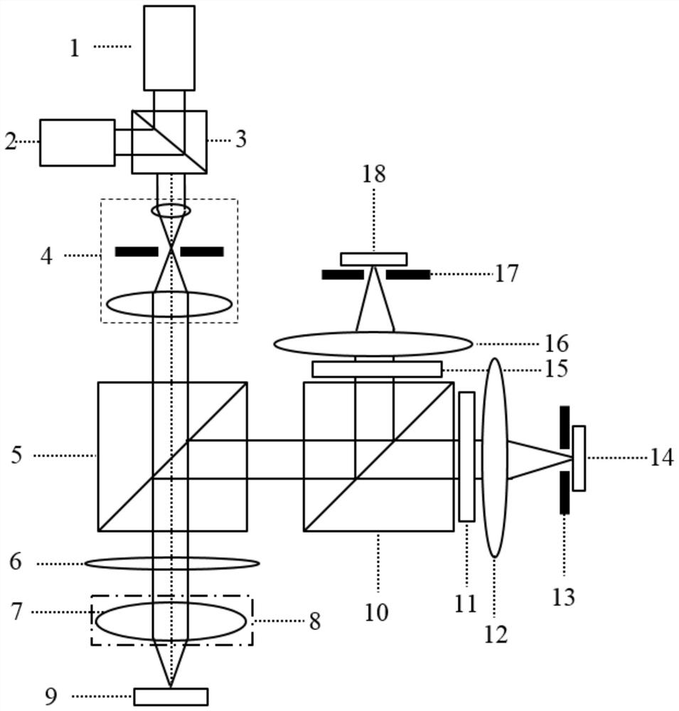
[0024] like figure 1 As shown, the dual-wavelength dual confocal laser microscopic measurement device of the present invention includes a laser, an incident light path, a reflection light path and a detection device. The laser includes a laser I1 and a laser II2, and the incident light path is: the two incident beam directions of the beam splitter 3 The laser I1 and the laser II2 are set respectively, and the direction of the outgoing beam of the beam splitter 3 is sequentially set with the collimator 4, the polarizing beam splitter 5, the quarter slide 6, the objective lens 7 and the sample stage 9, and the laser I1 and the laser II2 respectively emit Two laser beams with different wavelengths, for example, the incident directions of laser I1 and laser II2 are perpendicular to each other, and the laser beam passes through beam splitter 3, collimator 4, polarizing beam spli...


PUM


Abstract

The invention discloses a dual-wavelength dual-confocal laser microscopic measurement device and a measurement method, relates to the technical field of optical precision detection, and aims to improve the axial resolution capability and the transverse resolution capability of a laser confocal system at the same time. According to the method, the dual-wavelength dual-confocal laser microscopic measurement device comprises lasers, an incident light path, a reflection light path and a detection device, a first laser I and a first laser II respectively emit laser beams with different wavelengths, and the laser beams are converged to a sample through a beam splitter, a collimator, a polarizing beam splitter, a quarter-wave slide and an objective lens; and the reflected light is reflected by the polarizing beam splitter after passing through the objective lens and the quarter-wave slide, is divided into two paths by the semi-reflecting and semi-transmitting mirror, and then enters the detector I and the detector II respectively for detection. According to the method, the detector I and the detector II are respectively arranged at positions conjugated with the focus of the objective lens, and the output obtained by multiplying the normalized axial response curves of the double detectors is used as the output of the confocal system, so the confocal system is suitable for optical high-resolution measurement.

Description

technical field [0001] The present invention relates to the technical field of optical precision detection, in particular to a multiplication-based laser microscopic measuring device and a measuring method using a double-wavelength double-confocal detection structure. Background technique [0002] Laser confocal technology is a high-resolution measurement technology commonly used in the fields of precision displacement measurement and biomedical detection. Compared with ordinary optical microscopes, laser confocal microscopes adopt the overall optical structure of point illumination-point detection, which effectively suppresses stray light. The impact on system imaging, its lateral resolution and axial resolution have been significantly improved. [0003] The traditional laser confocal measurement technology uses the extreme point of the axial response curve of the confocal system to measure the displacement of the sample surface at fixed focus and height. Since the light in...

Claims


Application Information

Patent Timeline
Patent Type & Authority Applications(China)
IPC IPC(8): G01N21/84G01N21/01
CPCG01N21/01G01N21/84
Inventor 马小军王琦王宗伟何智兵唐兴胡勇叶成钢高党忠
Owner LASER FUSION RES CENT CHINA ACAD OF ENG PHYSICS
Why Eureka
Try Eureka