Input optical signal generating device for optical fiber array and photoetching system

A signal generating device and optical fiber array technology, applied in the optical field, can solve the problems of high cost of optical fiber switches, sensitive working wavelength, slow response speed, etc., and achieve the effects of low cost, fast response speed and strong applicability

Pending Publication Date: 2021-07-30
ZHEJIANG LAB +1
View PDF6 Cites 1 Cited by
  • Summary
  • Abstract
  • Description
  • Claims
  • Application Information

AI Technical Summary

Problems solved by technology

[0005] To sum up, in the current system that uses a large-scale optical fiber array and needs to independently control each optical fiber switch, there are problems such as high cost of optical fiber switches, slow response speed, and sensitivity to operating wavelengths.

Method used


Image

  • Input optical signal generating device for optical fiber array and photoetching system
  • Input optical signal generating device for optical fiber array and photoetching system
  • Input optical signal generating device for optical fiber array and photoetching system

Examples


Embodiment Construction

[0027] In order to explain the purpose, technical solutions and advantages of the present invention more clearly, the present invention will be further described in detail below in conjunction with the embodiments and accompanying drawings.

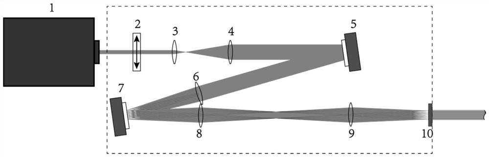
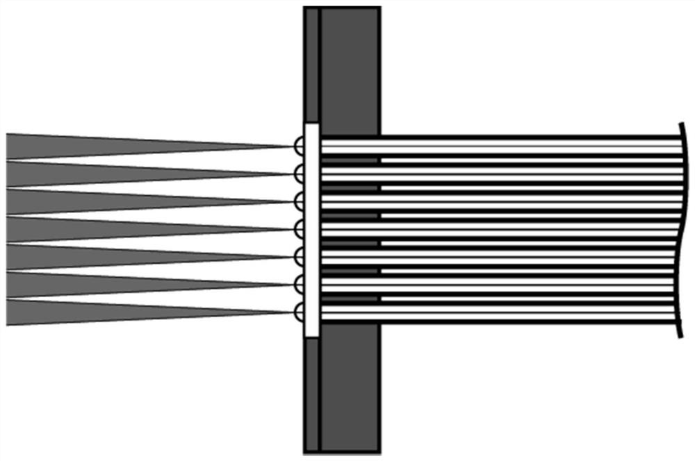
[0028] Such as figure 1 As shown, the present invention is an input optical signal generating device for an optical fiber array, which consists of a laser light source 1, a half-wave plate 2, a lens one 3, a lens two 4, a reflective spatial light modulator 5 (SLM), and a lens three 6 , digital micromirror device 7 (DMD), lens four 8, lens five 9, microlens array 10 (MLA) and optical fiber input end fixing device.

[0029] The laser light source 1 emits linearly polarized light, and the laser beam is modulated to the linear polarization direction required by the reflective spatial light modulator 5 through the half-wave plate 2, and then expanded and collimated by the lens 1 3 and the lens 2 4 before being directed toward the Reflective s...


PUM

PropertyMeasurementUnit
angle of incidenceaaaaaaaaaa

Abstract

The invention discloses an input optical signal generating device for an optical fiber array and a photoetching system. The input optical signal generating device is composed of optical components such as a spatial light modulator, a digital micro-mirror device and a micro-lens array. An incident single laser beam is modulated into a multi-beam array through the spatial light modulator, then any sub-beam in the multi-beam array is reflected into a corresponding micro-lens in a micro-lens array through a digital micro-lens device, and each sub-beam is focused through the micro-lens and then is incident into an optical fiber in an optical fiber array. Through programming control of the digital micro-mirror device, high-speed switching of on-off of each path of input optical signal in the optical fiber array can be realized. According to the invention, light source power can be effectively utilized to carry out multi-path light beam splitting and couple into the optical fiber array, and independent and controllable high-speed optical switch signal input of each optical fiber in the optical fiber array can be realized. The device can be used as a key device to be applied to the fields of communication, sensing, imaging, optical micromachining and the like based on optical fibers.

Description

technical field [0001] The invention belongs to the field of optical technology, and in particular relates to an input optical signal generating device and a photoetching system for an optical fiber array. Background technique [0002] Optical switching devices play a pivotal role in many fiber-based optical systems. For example, in the fields of optical fiber communication, sensing, imaging, and optical microprocessing, it is necessary to realize operations such as transmitting and receiving a large number of pulsed optical signals or continuous optical signals. The currently commercially available optical switching devices for optical fibers mainly include microelectromechanical system (MEMS) optical switches, electro-optical (EOM) switches, and acousto-optic (AOM) switches. Since the MEMS optical switch controls the on-off of the optical fiber optical path through the movement of the micro-machine, its switching speed is limited. At present, the switching time of the hig...

Claims


Application Information

Patent Timeline
Patent Type & Authority Applications(China)
IPC IPC(8): G02B6/35G02B6/27G03F7/20
CPCG02B6/3512G02B6/2753G02B6/2706G03F7/2057G03F7/2053G03F7/70391G03F7/70233
Inventor 匡翠方罗昊李海峰刘旭魏震马程鹏
Owner ZHEJIANG LAB
Why Eureka
Try Eureka