Laser scanning microscopic measurement device and method thereof

A technology of microscopic measurement and laser scanning, which is applied in the direction of microscope, optics, optical components, etc., can solve the problems of easily causing diffraction and detecting small pinholes, etc.

Pending Publication Date: 2021-07-30
SUZHOU DELPHI LASER +1
View PDF0 Cites 1 Cited by
  • Summary
  • Abstract
  • Description
  • Claims
  • Application Information

AI Technical Summary

Problems solved by technology

In order to improve the vertical resolution, the detection pinhole is small, which is easy to cause diffraction. The image points of different object points of the sample on the detection surface of the photomultiplier tube have deviations, but the position of the detection pinhole is fixed, so the object point on the axis is different from the object point on the side axis. point deviation

Method used


Image

  • Laser scanning microscopic measurement device and method thereof
  • Laser scanning microscopic measurement device and method thereof
  • Laser scanning microscopic measurement device and method thereof

Examples


Embodiment 1

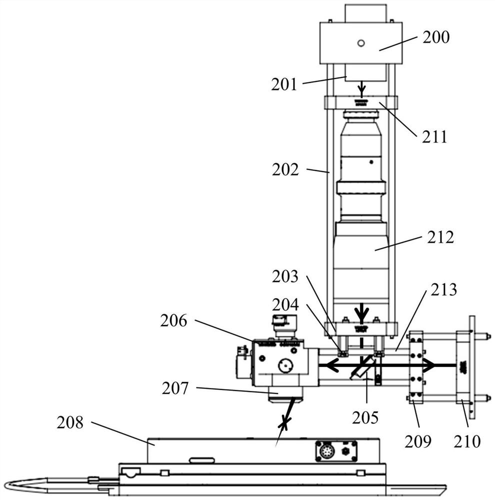
[0057]A 405nm laser 201 with a maximum power of 200mW (Changchun New Industry Optoelectronics Technology Co., Ltd., model MDL-XS-405) emits laser light with a diameter of 1.2mm, and passes through a beam expander 212 with a variable magnification of 2 to 5 times (Solebo, model BE -02-05-A) After the spot size is enlarged, it is reflected into the galvanometer 206 by the half mirror 205, and the galvanometer 206 controls the two-dimensional deflection of the laser, and the galvanometer with sensor measurement is used to allow the galvanometer mirror to work in a closed loop And can output the coordinates of the galvanometer. After scanning the objective lens 207, it focuses on the sample on the three-dimensional translation stage 208. The three-dimensional translation stage is composed of a two-dimensional translation stage and a piezoelectric ceramic Z-axis unit. The two-dimensional movement of the axis and the Y axis, the piezoelectric ceramic Z-axis unit (Solebo, model MZS50...

Embodiment 2

[0065] Example 2: Measurement of peak and valley values ​​of scratches by laser scanning microscopy.

[0066] Piezoelectric ceramics move Z-axis displacement 20μm, step size 0.25μm. At each Z-axis coordinate, a scanning objective lens with a focal length of 4 mm is used to scan the surface of the glass sample, with a single scanning format of 282.6 μm×210 μm, and the scanning angles in the X-Y directions are 4.0° and 3.0°, respectively. Measuring the surface topography photos of scratches as image 3 As shown, the maximum height value Rp of each point in this area is 2.65 μm, the minimum height value Rv of each point in this area is -2.72 μm, and the peak-to-valley value of scratches is equal to Rp–Rv=5.4 μm.

Embodiment 3

[0068] Under different virtual pinhole sizes, according to P S (z) The relationship between the normalized power calculated by the formula and the axial position is as follows Figure 4 shown. The virtual pinhole size corresponding to curve a and curve b is the magnification of the scanning objective lens multiplied by the beam waist size and the beam waist size respectively. The half-height width of curve a is larger than curve b, so the smaller the virtual pinhole size, the better the longitudinal Z-axis accuracy. high. However, the smaller the size, the lower the intensity, which requires a high magnification and sufficient sensitivity of the detection module. To improve the longitudinal precision, in addition to reducing the size of the virtual pinhole, it can also be achieved by reducing the focal length of the scanning objective lens.


PUM


Abstract

The invention relates to a laser scanning microscopic measurement device and method. A semi-reflecting and semi-transmitting mirror is arranged on an output light path of a laser, a galvanometer and a scanning objective lens are sequentially arranged on a reflection light path of the semi-reflecting and semi-transmitting mirror, and a detection module is arranged on a transmission light path; the laser emits laser, the laser enters the galvanometer through the semi-reflecting and semi-transmitting mirror, the galvanometer controls the laser to perform two-dimensional deflection, the laser is focused on a sample on the three-dimensional displacement table after passing through the scanning objective lens, and the laser is reflected after entering the sample, returns to the scanning objective lens and the galvanometer and then enters the detection module after passing through the semi-reflecting and semi-transmitting mirror; the detection module obtains images under different X-Y-Z coordinates, takes one or more CCD elements as virtual pinholes, obtains light intensity of a virtual pinhole area with the maximum light intensity in each image, obtains light intensity values under different X-Y-Z coordinates, obtains a Z coordinate corresponding to the maximum light intensity under any X-Y coordinate, that is, depth distribution of an X-Y plane, and measures surface appearance information of scratches and roughness.

Description

technical field [0001] The invention relates to a laser scanning microscopic measuring device and a method thereof. Background technique [0002] Monograph Handbook of Image and Video Processing (Second Edition) Chapter 10 Section 9 Confocal microscope page 1293, "Laser Scanning Confocal Microscopy Technology" page 4, "Laser Scanning Confocal Microscopy" page 2 are all published Laser Scanning Confocal Microscopy Light Path Diagram; Laser Scanning Confocal Microscopy Technology, p. Chapter 5 Introduction to the performance of each company's instruments, the optical components of the laser scanning confocal microscope include photomultiplier tubes and detection pinholes, lasers and light source pinholes. In order to improve the vertical resolution, the detection pinhole is small, which is easy to cause diffraction. The image points of different object points of the sample on the detection surface of the photomultiplier tube have deviations, but the position of the detection ...

Claims


Application Information

Patent Timeline
Patent Type & Authority Applications(China)
IPC IPC(8): G02B21/00G02B21/06G02B21/36
CPCG02B21/0048G02B21/0032G02B21/008G02B21/06G02B21/362
Inventor 赵裕兴王承伟徐海宾
Owner SUZHOU DELPHI LASER
Why Eureka
Try Eureka