
Method and device for cleaning contaminated used oil

A technology of equipment and melting bath, which is applied in the field of equipment for purifying polluted waste oil, and can solve problems such as methods for waste oil that have not yet been disclosed

Inactive Publication Date: 2021-07-30
BIOFABRIK HOYERSWERDA GMBH
View PDF13 Cites 1 Cited by
  • Summary
  • Abstract
  • Description
  • Claims
  • Application Information

AI Technical Summary

Problems solved by technology

[0010] The use of metal baths for the treatment of waste oil as a raw material has not been disclosed in the above literature sources

Method used


Image

  • Method and device for cleaning contaminated used oil
  • Method and device for cleaning contaminated used oil
  • Method and device for cleaning contaminated used oil

Examples


Embodiment Construction

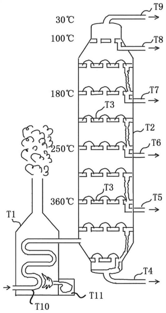
[0058] As shown in Fig. 1, according to the prior art, the crude oil is heated above 360°C in the tube furnace T1, so that the components are largely evaporated. They enter a distillation column T2 built from a plurality of bubble-cap trays T3. Distillates T4 to T9 of the individual fractions are collected in bubble-cap tray T3. It can be seen that the pipe T10 leading the waste oil is in direct contact with the hot gas generated in the combustion chamber T11. In terms of temperature, the hot gas is unevenly distributed in the tube furnace T1 so that the tube T10 is partially overheated. The heat capacity of the hot gas is also low, so that it has to work with higher temperature differences, ie intense heating of the hot gas, which in turn leads to overheating of the tube T10. This cannot avoid the internal slagging of the tube T10, which must be removed during routine maintenance. Such maintenance in turn prohibits the mobile use of such equipment.

[0059] As shown in Fi...


PUM


Abstract

The invention relates to a method and a device for cleaning contaminated used oil, in which starting material is heated to the gas phase and the resultant vapor is rectified, with purified oil being removed as condensate from a drain in a rectification column. The problem addressed by the invention is that of providing a method and device for purifying contaminated used oil, which method enables efficient operation even in the smallest of systems, such that a compact system configuration and thus in particular mobile use by a container structure is made possible. The invention also addresses the problem of reducing the cost required for servicing. The problem according to the invention is solved in that used oil is subjected to an evaporation process by at least indirectly placing the starting material in contact with a melting bath, the melting temperature of which is above the evaporation temperature but below the ignition temperature of the used oil, and by rectifying the vapor in the rectification column.

Description

technical field [0001] The present invention relates to a process for treating liquid oily residues, such as waste oil, polluted diesel, fuel oil or bunker oil, collectively referred to herein as polluted waste oil, as raw material in said process. Waste oils can be purified by pure distillation without altering the molecular structure. However, the invention can also be used in temperature ranges in which so-called cracking occurs, ie the breaking of long molecular chains into shorter molecular chains. [0002] The invention relates to a method for the purification of contaminated waste oil, wherein the raw material is heated into the gas phase and the resulting steam is rectified, wherein the purified oil is removed as condensate from a discharge in the rectification column. [0003] The invention also relates to a device for purifying polluted waste oil, comprising a main reactor and a rectification tower connected thereto. Background technique [0004] DE 198 20 635 A1...

Claims


Application Information

Patent Timeline
Patent Type & Authority Applications(China)
IPC IPC(8): B01D1/00B01D1/02B01D1/14B01D1/30B01D3/14B01D3/32C10G9/34C10G7/00
CPCB01D3/148B01D3/322B01D1/0052B01D1/305B01D1/02B01D1/14B01D1/30C10G9/34C10G7/006B01D3/06C10G2300/1007
Inventor M·里克特
Owner BIOFABRIK HOYERSWERDA GMBH
Learn More