
Reheating type multi-section heating coke oven combustion system

A multi-stage heating and combustion system technology, applied in the coke oven field, can solve the problems of unfavorable long-term stability of the combustion chamber structure, unfavorable segmental air supply ratio, and high requirements for masonry error control, so as to improve heating uniformity and reduce air pollution , The effect of convenient construction

Pending Publication Date: 2021-08-03
ACRE COKING & REFRACTORY ENG CONSULTING CORP DALIAN MCC
View PDF0 Cites 0 Cited by
  • Summary
  • Abstract
  • Description
  • Claims
  • Application Information

AI Technical Summary

Problems solved by technology

For the coke oven combustion system that adopts the staged supply of combustion-supporting air, the air supply generally adopts a Y-shaped channel structure, that is, the first section of air supply inlet is located at the bottom of the combustion chamber, and the other sections of air supply inlets are respectively located along the height direction. Fireway partition wall; this structure itself is relatively complicated, which is not conducive to controlling the ratio of segmented air supply
In addition, the space at the bottom of the combustion chamber is relatively narrow, and the first section of air supply inlet is located at the bottom of the vertical fire channel, which is not conducive to the long-term stability of the combustion chamber structure, and the requirements for masonry error control are high, which makes the construction more difficult

Method used


Image

  • Reheating type multi-section heating coke oven combustion system
  • Reheating type multi-section heating coke oven combustion system
  • Reheating type multi-section heating coke oven combustion system

Examples


Embodiment Construction

[0021] The specific embodiment of the present invention will be further described below in conjunction with accompanying drawing:

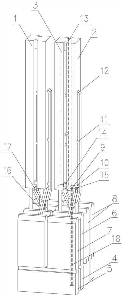
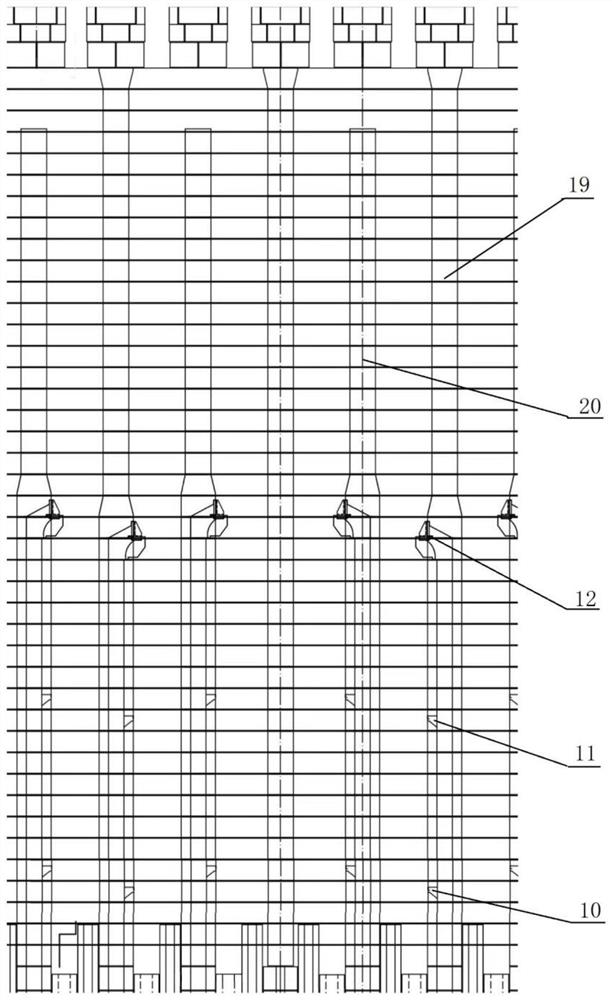
[0022] Such as figure 1 , figure 2 As shown, a reheating multi-stage heating coke oven combustion system according to the present invention, the coke oven is composed of a regenerator, a chute, a combustion chamber 1, a carbonization chamber and a furnace top area; the combustion chamber 1 and the carbonization chamber are arranged alternately , the combustion chamber 1 is made up of many pairs of double-connected fire passages, and the two adjacent double-connected fire passages are separated by a double-connected fire passage partition wall 19. The vertical fire passages are separated by a fire passage partition wall 20; coke oven gas supply inlet 9, multi-stage air supply inlet, and blast furnace gas supply inlet 15 are respectively set in each vertical fire passage; the multi-stage air supply inlet is arranged on one side On the double fire...


PUM


Abstract

The invention relates to a reheating type multi-section heating coke oven combustion system. A coke oven gas supply inlet, multiple sections of air supply inlets and a blast furnace gas supply inlet are respectively formed in each vertical flue of a duplex vertical flue. The multiple sections of air supply inlets are formed in a duplex vertical flue partition wall and a vertical flue partition wall on one side respectively, and the first section of air supply inlet is formed in the lower portion of the duplex vertical flue partition wall or the lower portion of the vertical flue partition wall and is higher than a waste gas circulation hole. The coke oven gas supply inlets and the blast furnace gas supply inlets are formed in the bottoms of the vertical flues. The system is suitable for a reheating coke oven which can use coke oven gas as a heat source and can also use blast furnace gas as a heat source. Compared with an existing reheating type coke oven structure, the first section of air supply inlet is formed in the lower portion of the duplex vertical flue partition wall or the vertical flue partition wall, the bottom space of a combustion chamber is effectively saved, the heating uniformity of the vertical flues in the height direction is improved, meanwhile, generation of nitric oxide is reduced, air pollution is reduced, the structure is simple, and coke oven gas pipe bricks can be conveniently dredged.

Description

technical field [0001] The invention relates to the technical field of coke ovens, in particular to a reheating type multi-stage heating coke oven combustion system. Background technique [0002] Modern coke ovens are mainly chamber-type coke ovens, which are composed of regenerators, ramps, combustion chambers, carbonization chambers and furnace top areas. With the development of coke oven technology and the upgrading of production equipment, higher requirements have been put forward for the production and operation of coke ovens, such as high-level heating uniformity, production capacity, and pollutant content in tail gas. [0003] At present, the new coke oven projects in China are mainly double-fired down-spray coke ovens. The fuel and air enter the combustion chamber from the lower part of the coke oven through the regenerator and the ramp for combustion, and then reach the combustion chamber through the descending fire. The bottom of the combustion chamber is discharg...

Claims


Application Information

Patent Timeline
Patent Type & Authority Applications(China)
IPC IPC(8): C10B21/00C10B21/10
CPCC10B21/00C10B21/10
Inventor 郝传松杨俊峰韩龙
Owner ACRE COKING & REFRACTORY ENG CONSULTING CORP DALIAN MCC
Learn More