A fully prefabricated steel-concrete composite floor system and its design calculation method

A prefabricated assembly and prefabricated concrete technology, applied in design optimization/simulation, floor slabs, instruments, etc., can solve the problem of high labor cost, low reusability of bottom form, and complicated construction process of detachable bottom form truss reinforced floor deck. And other issues

Active Publication Date: 2021-09-10
CENT RES INST OF BUILDING & CONSTR CO LTD MCC GRP +1
View PDF9 Cites 1 Cited by
  • Summary
  • Abstract
  • Description
  • Claims
  • Application Information

AI Technical Summary

Problems solved by technology

The traditional steel-cast-in-place concrete floor has good mechanical properties and stiffness, but it has problems such as on-site formwork operations, steel bar binding operations, and large concrete pouring operations, slow construction operations, high labor costs, and serious environmental pollution. Does not conform to the development concept of building industrialization and green building
In order to meet the needs of industrialized construction, the floor forms of the existing prefabricated steel-concrete composite floors mainly include traditional truss-reinforced floor slabs, detachable bottom formwork truss-reinforced floor slabs, and laminated slab composite floors, etc. However, market verification shows that the above-mentioned The product is still not a mature solution for prefabricated residential building floors: traditional truss-reinforced floor slabs have poor aesthetics due to exposed profiled steel plates, hinder decoration, and have low consumer acceptance; the construction process of truss-reinforced floor slabs with removable bottom formwork is complicated , the actual reusability of the bottom form is not high, and the cost control is difficult; while the actual thickness of the laminated slab composite floor is often greater than 150mm, and the adaptability in residential buildings is low

Method used


Image

  • A fully prefabricated steel-concrete composite floor system and its design calculation method
  • A fully prefabricated steel-concrete composite floor system and its design calculation method
  • A fully prefabricated steel-concrete composite floor system and its design calculation method

Examples


Embodiment Construction

[0061] In order to make the purpose, technical solutions and advantages of the embodiments of the present invention more clear, the embodiments of the present invention will be further described in detail below in conjunction with the embodiments and the accompanying drawings. Here, the exemplary embodiments and descriptions of the present invention are used to explain the present invention, but not to limit the present invention.

[0062] In describing the present invention, it is to be understood that the terms "comprises / comprising", "consisting of" or any other variation thereof are intended to cover a non-exclusive inclusion such that a product, device, A process or method includes not only those elements, but may also include other elements not expressly listed, or elements inherent in such a product, apparatus, process, or method, as required. Without further limitations, an element defined by the phrase "comprising / comprising...", "consisting of... does not exclude the...


PUM


Abstract

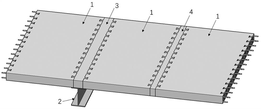
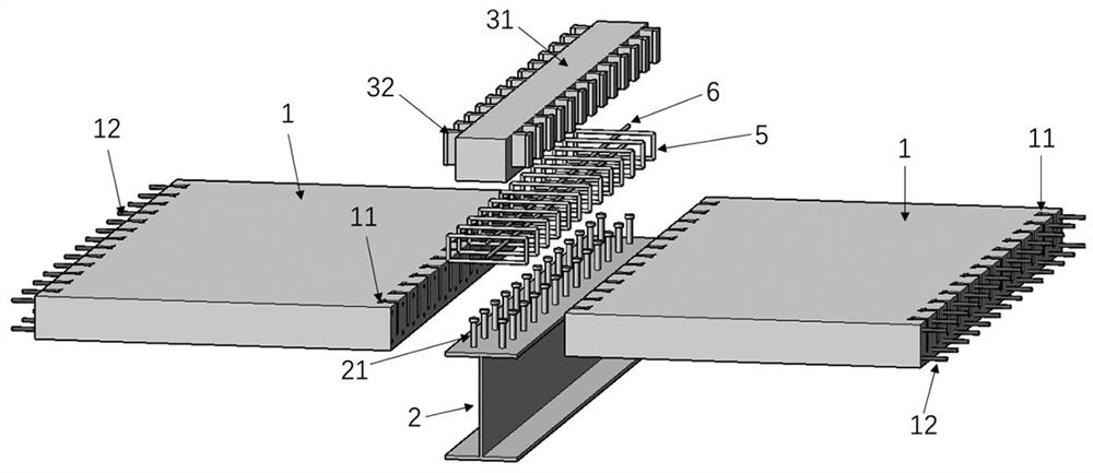
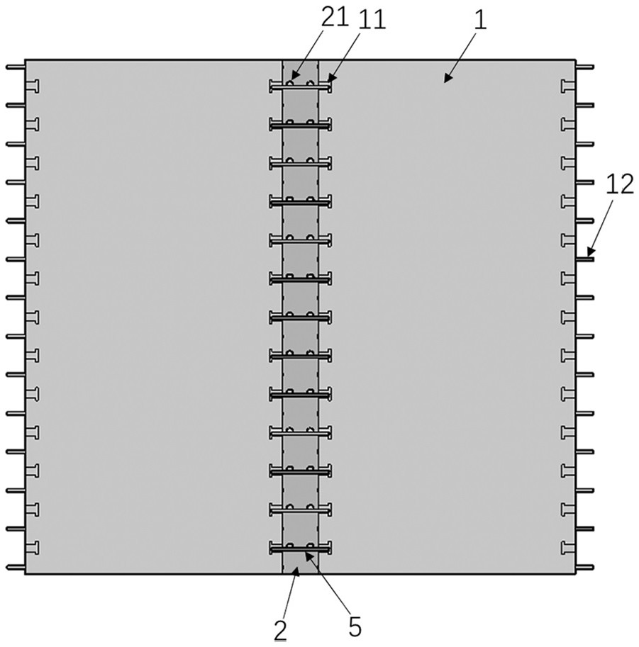
The invention discloses a fully prefabricated assembled steel-concrete composite floor system and a design calculation method. The floor system includes a prefabricated concrete floor (1), H-shaped steel beams (2), beam-slab UHPC mortise and tenon connection nodes ( 3) UHPC mortise and tenon connection joints (4) with slabs, in which: the two sides of the precast concrete floor (1) are provided with shear slots (11) along the thickness direction of the slab; the upper flange of the H-shaped steel beam (2) is Stud connectors (21) are welded; two precast concrete floors (1) and H-shaped steel beams (2) are connected by beam-slab UHPC mortise and tenon joints (3); between two adjacent precast concrete floors (1) The board-to-board UHPC mortise and tenon joints (4) are used to connect. The design of the present invention adopts ultra-high-performance concrete UHPC to connect the prefabricated concrete floor, the H-shaped steel beam and the prefabricated concrete floor. The prefabricated floor system has the advantages of simple structure, reliable performance, convenient and fast construction, and environmental protection.

Description

technical field [0001] The invention relates to the technical field of building structure connection construction, in particular to a fully prefabricated steel-concrete composite floor system and a design calculation method. Background technique [0002] As an important part of the overall lateral force resistance system of the building structure, the floor not only needs to bear the constant and live loads of the floor, but also effectively transmit the horizontal earthquake action and wind load to other lateral force resistant components. The traditional steel-cast-in-place concrete floor has good mechanical properties and stiffness, but it has problems such as on-site formwork operations, steel bar binding operations, and large concrete pouring operations, slow construction operations, high labor costs, and serious environmental pollution. It does not conform to the development concept of building industrialization and green building. In order to meet the needs of indust...

Claims


Application Information

Patent Timeline
Patent Type & Authority Patents(China)
IPC IPC(8): E04B5/02E04B5/10E04B1/682G06F30/13G06F30/20
CPCE04B1/6801E04B5/023E04B5/10G06F30/13G06F30/20G06F2119/14
Inventor 刘晓刚郑明召王皓岳清瑞刘洁
Owner CENT RES INST OF BUILDING & CONSTR CO LTD MCC GRP
Why Eureka
Try Eureka