A method for calibrating an infrared thermal imager based on powder bed fusion

A technology of infrared thermal imaging camera and calibration method, which is applied in the field of additive manufacturing, can solve the problems of laser beam energy center offset, unaccounted for, and influence on real-time temperature field detection, and achieve the effect of high accuracy and simple calibration method

Active Publication Date: 2022-08-02
HUAZHONG UNIV OF SCI & TECH
View PDF3 Cites 0 Cited by
  • Summary
  • Abstract
  • Description
  • Claims
  • Application Information

AI Technical Summary

Problems solved by technology

For the laser selective melting process, there are the following characteristics: the working cavity is airtight during processing; the observation angle will be affected by the processing smoke and dust under different airflows; the position change of the thermal imager caused by equipment vibration and deformation, etc. It is impossible to add a calibration plate to re-calibrate the thermal imager that has been misplaced or needs to be displaced during the processing, which affects the detection of real-time temperature field; secondly, the currently available calibration methods such as laser scanning calibration patterns do not take into account the thermal imager The identified laser energy center is not the real laser light emitting position, and the laser will cause the energy center of the laser beam to shift under the influence of defocus and incident angle, causing the center of the spot diffusion ring acquired by the infrared thermal imager to actually be on the oblique section of the laser The position of the center of mass of the energy distribution is not the laser incident point

Method used


Image

  • A method for calibrating an infrared thermal imager based on powder bed fusion
  • A method for calibrating an infrared thermal imager based on powder bed fusion
  • A method for calibrating an infrared thermal imager based on powder bed fusion

Examples


Embodiment Construction

[0042] In order to make the objectives, technical solutions and advantages of the present invention clearer, the present invention will be further described in detail below with reference to the accompanying drawings and embodiments. It should be understood that the specific embodiments described herein are only used to explain the present invention, but not to limit the present invention. In addition, the technical features involved in the various embodiments of the present invention described below can be combined with each other as long as there is no conflict with each other.

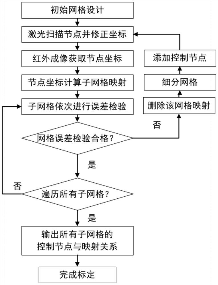
[0043] like figure 1 As shown, a method for calibrating an infrared thermal imager with powder bed fusion specifically includes the following steps:

[0044] Step 1: Design the calibration method according to the characteristics of the laser selective melting process

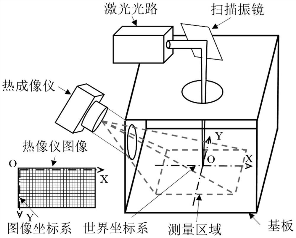
[0045] Establish a calibration coordinate system. Firstly, the world coordinate system on the substrate of the laser scanning sys...


PUM


Abstract

The invention belongs to the technical field of additive manufacturing, and discloses a method for calibrating an infrared thermal imager by powder bed fusion. It includes the following steps: S1 divides the actual processing area of ​​the substrate into a grid, and obtains the two-dimensional coordinates of each grid node; S2 emits multiple laser beams, and the laser incident point corresponds to a grid node; uses an infrared thermal imager to photograph the substrate on the substrate. S3 is the transformation matrix between the two-dimensional coordinates of each grid node and the image coordinates; S4 verifies whether the transformation matrix is ​​accurate; S5 is inaccurate, re-divide the network grid, return to step S3, until the transformation matrix meets the requirements, and obtain the transformation matrix corresponding to each grid, and complete the calibration of the infrared thermal imager. The invention ensures that the infrared thermal imager can be simply re-calibrated after being forced to move in the laser processing process, and the mapping relationship with the coordinate system of the laser scanning system is directly established, with high accuracy.

Description

technical field [0001] The invention belongs to the technical field of additive manufacturing, and more particularly, relates to a method for calibrating an infrared thermal imager by powder bed fusion. Background technique [0002] Compared with other additive manufacturing technologies, powder bed fusion technology (PBF) can directly manufacture parts with high precision and density close to 100%, especially for complex structural parts with high forming freedom and high precision. Powder bed fusion technology uses a high-energy heat source such as a laser to melt the powder material on the powder bed layer by layer according to the data information of each layer of the solid model of the processed part. Due to the conventional processing, the diameter of the spot size is between 50-200 μm, and the powder material is relatively small. The rapid melting and solidification process is experienced in the light spot area, which produces large transient thermal stress and temper...

Claims


Application Information

Patent Timeline
Patent Type & Authority Patents(China)
IPC IPC(8): G06T7/80G06T7/70G01J5/90
CPCG06T7/80G06T7/70G01J5/00G01J2005/0077G01J5/80
Inventor 张李超胡祺吴甲民王森林李萌吴亚茹何骏驰史玉升
Owner HUAZHONG UNIV OF SCI & TECH
Why Eureka
Try Eureka