
Electrolytic capacitor working electrolyte leakage-proof device

A technology of electrolytic capacitors and leak-proof devices, which is applied in the field of capacitors and can solve problems such as electrolyte leakage, electrolyte storage, and electrolyte inability to absorb it

Active Publication Date: 2021-08-03
NANTONG HUAYU ELECTRONICS
View PDF4 Cites 2 Cited by
  • Summary
  • Abstract
  • Description
  • Claims
  • Application Information

AI Technical Summary

Problems solved by technology

[0005] The invention provides an anti-leakage device for the working electrolyte of an electrolytic capacitor. One of the purposes is to have the ability to cool down the temperature inside the capacitor, ensure the uniform surface temperature of the capacitor, and solve the problem of electrolysis caused by excessive local temperature on the surface of the capacitor. The problem of liquid leakage; another purpose is to solve the problem that the electrolyte cannot be adsorbed and stored when it leaks, so as to avoid the effect of flowing to the outside of the capacitor when the electrolyte leaks

Method used


Image

  • Electrolytic capacitor working electrolyte leakage-proof device
  • Electrolytic capacitor working electrolyte leakage-proof device
  • Electrolytic capacitor working electrolyte leakage-proof device

Examples


Embodiment 1

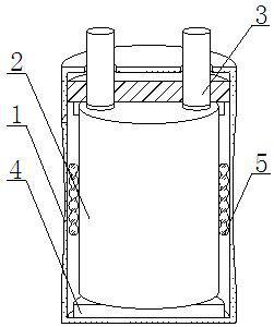
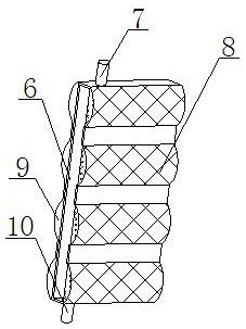
[0037] like Figure 1-6 As shown, the present invention provides a kind of anti-leakage device for working electrolyte of electrolytic capacitor, comprising capacitor body 1, aluminum shell 2 and electrode tube 3, the bottom of electrode tube 3 is plugged with the top of aluminum shell 2, and the top of electrode tube 3 The outer wall runs through the inner wall of the capacitor body 1, the aluminum shell 2 is located inside the capacitor body 1, the outer wall of the aluminum shell 2 is overlapped with an electrolyte adsorption device 5, and the bottom of the aluminum shell 2 is fixedly connected with a heat conduction seat 4, and the heat conduction seat 4 is fixedly installed with a support column 23, and the outer wall of the support column 23 is fixedly installed with a heat conduction plate 24, the inner wall of the heat conduction plate 24 is overlapped with the outer wall of the aluminum shell 2, and the electrolyte adsorption device 5 includes a built-in frame 6 and T...

Embodiment 2

[0040] like Figure 1-6As shown, on the basis of Embodiment 1, the present invention provides a technical solution: preferably, the inner wall of the liquid storage device 9 is provided with an arc-shaped slide plate 14 and a sealing device 16, and both ends of the arc-shaped slide plate 14 are connected to the liquid storage The inner wall of the device 9 is slidably connected, the bottom of the sealing device 16 is fixedly connected with the inner wall of the liquid storage device 9, the bottom of the curved slide 14 is overlapped with an air pressure bag 15, and the bottom of the air pressure bag 15 is fixedly connected with the bottom of the inner wall of the liquid storage device 9 , the inner wall of the sealing device 16 is fixedly installed with a gas expansion telescopic assembly 19, the output end of the gas expansion telescopic assembly 19 is fixedly connected with a telescopic plate 20, the top of the telescopic plate 20 is fixedly mounted with a baffle plate 21, an...

Embodiment 3

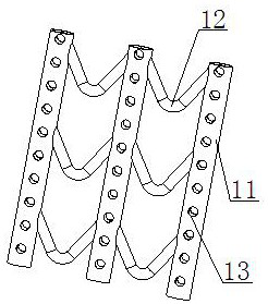
[0044] like Figure 1-6 As shown, on the basis of Example 1, the present invention provides a technical solution: preferably, the inner wall of the built-in frame 6 is provided with a microporous conduit 11 and a transition tube 12, and the transition tube 12 is arranged between the microporous conduits 11, And the two ends of the transition pipe 12 are connected through the outer wall of the microporous conduit 11, the outer wall of the microporous conduit 11 is provided with a through hole 13, the upper and lower ends of the microporous conduit 11 are fixedly connected with the inner wall of the built-in frame 6, and the inner wall of the built-in frame 6 The top is connected with the first connector 7, the bottom of the built-in frame 6 is connected with the second connector 10, the outer walls of the first connector 7 and the second connector 10 are fixedly connected with the outer wall of the heat conduction plate 24, and the second The first connecting piece 7 and the se...


PUM


Abstract

The invention discloses an electrolytic capacitor working electrolyte leakage-proof device, and relates to the technical field of capacitors. The electrolytic capacitor working electrolyte leakage-proof device comprises a capacitor body, an aluminum shell and an electrode tube. The bottom of the electrode tube is in plug-in connection with the top of the aluminum shell, the outer wall of the electrode tube penetrates through the inner wall of the capacitor body, and the aluminum shell is arranged in the capacitor body. The outer wall of the aluminum shell is in lap joint with an electrolyte adsorption device, the bottom of the aluminum shell is fixedly connected with a heat conduction base, and the electrolyte adsorption device comprises a built-in frame and a liquid transition foil. Through cooperation of the heat conduction plate and the heat conduction seat, the temperature of the surface of the aluminum shell can be reduced, electrolyte leakage caused by over-high local temperature of the surface of the aluminum shell is prevented, and the temperature of the surface of the aluminum shell can be homogenized, so that the possibility that the electrolyte leaks outwards due to over-high external temperature is firstly avoided; the problem that leakage of the electrolyte is influenced by external factors is solved.

Description

technical field [0001] The invention relates to the technical field of capacitors, in particular to an anti-leakage device for working electrolyte of an electrolytic capacitor. Background technique [0002] A capacitor is an element that stores electricity and energy. One conductor is surrounded by another conductor, or the electric field lines emitted by one conductor are all terminated in another conductor. The device can act as a buffer protection for the capacitor. There are following problems at prior art: [0003] 1. The reason for the leakage of the electrolyte in the capacitor is generally that the internal pressure voltage is too large, which leads to a certain part of the capacitor's internal temperature being too high, resulting in damage to the aluminum shell that wraps the yin and yang foils, resulting in electrolysis. liquid leakage; [0004] 2. When the electrolyte leaks, if the electrolyte cannot be adsorbed, the electrolyte will leak to the surface of the...

Claims


Application Information

Patent Timeline
Patent Type & Authority Applications(China)
IPC IPC(8): H01G9/00H01G9/08H01G9/004H01G9/145H01G2/08
CPCH01G9/0003H01G9/08H01G9/004H01G9/145
Inventor 杨建华
Owner NANTONG HUAYU ELECTRONICS
Learn More