
Waste gas treatment device

A technology for treating device and waste gas, which is applied in the directions of air quality improvement, filtration of dispersed particles, separation of dispersed particles, etc., can solve the problems of low investment cost and operating cost, difficult treatment of kitchen waste gas, etc., and achieve the effect of low investment and operating cost.

Inactive Publication Date: 2021-08-06
北京赛富威环境工程技术有限公司
View PDF6 Cites 2 Cited by
  • Summary
  • Abstract
  • Description
  • Claims
  • Application Information

AI Technical Summary

Problems solved by technology

[0017] The invention provides a waste gas treatment device, which effectively solves the difficult technical problems of industrial malodorous waste gas and kitchen waste gas, and has a removal efficiency of more than 98% for particulate pollutants and malodorous organic matter in industrial waste gas. The removal efficiency of oil fume and organic pollutants from kitchen fume exhaust gas is greater than 99%, without any secondary pollution, and the investment cost and operation cost are low

Method used


Image

  • Waste gas treatment device
  • Waste gas treatment device

Examples


Embodiment

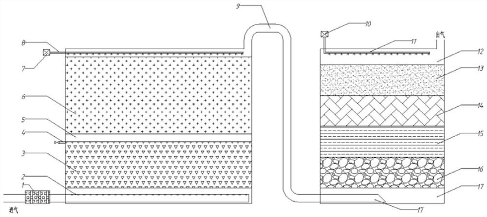
[0065] Such as figure 1 As shown, Embodiment 1 of the present invention provides a waste gas treatment device, including: a filtration system, a biological treatment unit, and a bioaugmentation and nutrient atomization reaction zone;

[0066] The filter system 1 is arranged on the outside of the bottom of the processing device, and is used to remove particulate pollutants (PM10) in the exhaust gas; avoid blocking the back-end system, and ensure the operation effect of the back-end system;

[0067] The biological treatment unit is built in the treatment device, and the bottom of the biological treatment unit is connected to the filter system, which is used to guide the waste gas in the filter system to pass through the lower biofilm reaction zone in the bacterial liquid in the biological treatment unit from bottom to top After the upper biofilm reaction zone located above the liquid surface layer of the bacterial solution and the microbial strains located on the top of the trea...

specific Embodiment

[0115] 1. Analyze the source of waste gas and confirm that it is industrial waste gas and / or cooking fume waste gas, and the industrial waste gas is determined to be the stench produced by hazardous waste warehouses, sewage treatment workshops, sludge drying workshops, production workshops, fermentation workshops or waste gas incinerators Gas or malodorous gas produced by landfill plants or industrial malodorous waste gas produced by other links;

[0116] 2. After determining the source of waste gas, further confirm the treatment volume of waste gas, main characteristic pollutants and concentrations, currently implemented emission standards, odor value and other indicators;

[0117] 3. Design the treatment device according to the gas volume, main characteristic pollutants and emission standards;

[0118]Fourth, according to the composition of waste pollutants, determine the optimal strain ratio, the type of filler for each unit, etc.;

[0119] 5. Deal with project implementat...


PUM


Abstract

The present invention provides a waste gas treatment device, which comprises: a filtration system for removing particulate pollutants in waste gas; a biological treatment unit which is used for guiding the waste gas in the filtering system to pass through the biological treatment unit from bottom to top and then further degrading and adsorbing organic matters in the waste gas; and a biological enhancement and nutrient atomization reaction area which is used for guiding the waste gas in the biological treatment unit from the bottom of the biological enhancement and nutrient atomization reaction area from bottom to top under the action of a filler layer, a bacterial liquid and nutrient storage area and a top atomization device so as to remove malodorous substances and organic matters in the waste gas to the maximum extent. The technical problem that industrial foul waste gas and kitchen waste gas are difficult to treat is effectively solved, and the investment and operation cost is low; the removal efficiency of organic pollutants in waste gas is 98% or above; the peculiar smell removal efficiency is greater than 99%; and the device is suitable for purifying industrial waste gas and kitchen oil fume waste gas.

Description

technical field [0001] The invention relates to the technical field of waste gas treatment, and relates to a waste gas treatment device, in particular to a treatment device and method for industrial malodorous waste gas and cooking fume waste gas. Background technique [0002] Industrial malodorous gas pollution refers to all gaseous substances that stimulate the olfactory organs, cause people's unpleasantness and damage the living environment. As a typical environmental hazard, it has been recognized by all countries in the world. Many developed countries have studied it as a separate pollution hazard and implemented special legislation to prevent it. The treatment of odor pollution has also been carried out earlier in foreign countries. In many industrial fields in Japan, Europe and the United States, technologies such as fixed-bed activated carbon adsorption and deodorization have a certain history. [0003] In recent years, my country has also begun to pay attention to ...

Claims


Application Information

Patent Timeline
Patent Type & Authority Applications(China)
IPC IPC(8): B01D53/84B01D53/44B01D46/00
CPCB01D53/84B01D53/44B01D46/00Y02A50/20
Inventor 舒孝喜温捷
Owner 北京赛富威环境工程技术有限公司
Learn More