Marine medium-and-high-speed oil-gas double-electric-control dual-fuel engine

A dual-fuel engine, medium-to-high-speed technology, applied in engine control, machine/engine, electrical control, etc., can solve the problem of failure to meet the emission limit requirements of marine engines, the engine cannot enter the dual-fuel mode state, and the replacement rate of dual-fuel engines is low and other issues, to achieve the effect of improving fuel substitution rate, ensuring safety, and stringent emission limit requirements

Pending Publication Date: 2021-08-06
淄柴机器有限公司
View PDF5 Cites 1 Cited by
  • Summary
  • Abstract
  • Description
  • Claims
  • Application Information

AI Technical Summary

Problems solved by technology

[0002] At present, the fuel supply of marine dual-fuel engines is generally controlled by mechanical pumps. For different engine loads and different working modes (fuel mode and dual-fuel mode), the engine can only adopt the same fuel supply advance angle, which cannot be performed independently. Combustion optimization leads to a low replacement rate of dual-fuel engines in the mechanical pump control mode, and poor emissions, which cannot meet the increasingly stringent emission limit requirements for marine engines
At present, mechanical pumps and electronically controlled pump dual-fuel engines generally use oil control and speed regulation. When the engine is in dual-fuel mode, the actual amount of injected fuel is small, resulting in fluctuations in engine speed, and the engine cannot enter dual-fuel mode under low load. At the same time, it also limits the room for increasing the gas substitution rate in dual-fuel mode

Method used


Image

  • Marine medium-and-high-speed oil-gas double-electric-control dual-fuel engine
  • Marine medium-and-high-speed oil-gas double-electric-control dual-fuel engine
  • Marine medium-and-high-speed oil-gas double-electric-control dual-fuel engine

Examples


Embodiment Construction

[0033] The present invention will be described in further detail below in conjunction with the accompanying drawings.

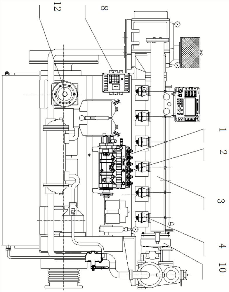
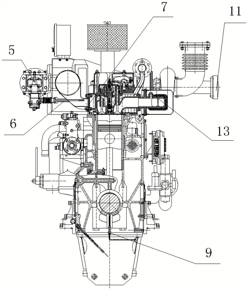
[0034] Such as figure 1 , 2 As shown, the high-pressure fuel injection electric control combination pump 1 is driven by the engine gear chamber through the coupling, and the fuel injection solenoid valve 2 is respectively installed at the oil outlet of the plunger of each cylinder, and its control is through the oil and gas dual control ECU 8. The fuel control part controls the fuel injection timing and fuel quantity; serial number 3 is the common rail pipe of the natural gas injection system, which has a double-wall structure, the inner side is the gas supply rail pipe, and the outer side is the ventilation pipe, and each cylinder is equipped with a gas injection solenoid valve 4. The opening and closing of the gas injection solenoid valve 4 is controlled by the gas part in the oil-gas dual control ECU 8, and the gas is directly injected to the air inlet of...


PUM


Abstract

The invention relates to a marine medium-high-speed oil-gas dual-electronic-control dual-fuel engine. The marine medium-high-speed oil-gas dual-electronic-control dual-fuel engine comprises a fuel high-pressure injection electronic-control combined pump, fuel injection electromagnetic valves and a natural gas injection system common rail pipe, wherein the fuel injection electromagnetic valves are arranged at the fuel outlet positions of plungers of all cylinders; the fuel injection time and the fuel quantity are controlled through a fuel control part in an oil-gas double-control ECU; each cylinder of the natural gas injection system common rail pipe is provided with a fuel gas injection electromagnetic valve respectively; opening and closing of the fuel gas injection electromagnetic valves are controlled through a fuel gas part in the oil-gas double-control ECU; and fuel gas is directly injected to a gas inlet of a cylinder cover through a corrugated pipe and a fuel gas injection pipe. Meanwhile, the invention discloses a working method of the marine medium-high-speed oil-gas dual-electronic-control dual-fuel engine. According to the working method, parameters such as required injection oil quantity and pulse width are automatically calculated according to hardware parameters of an electronic control pump hardware parameter ECU, and oil quantity correction is carried out based on the rotating speed and exhaust temperature difference, so that the rotating speed adjusting function of the engine is achieved.

Description

technical field [0001] The invention relates to the technical field of marine engines, in particular to a medium and high-speed oil-gas dual-electric control dual-fuel engine for marine applications. Background technique [0002] At present, the fuel supply of marine dual-fuel engines is generally controlled by mechanical pumps. For different engine loads and different working modes (fuel mode and dual-fuel mode), the engine can only adopt the same fuel supply advance angle, which cannot be performed independently. Combustion optimization leads to a low replacement rate of dual-fuel engines in the mechanical pump control mode, and poor emissions, which cannot meet the increasingly stringent emission limit requirements for marine engines. At present, mechanical pumps and electronically controlled pump dual-fuel engines generally use oil control and speed regulation. When the engine is in dual-fuel mode, the actual amount of injected fuel is small, resulting in fluctuations in...

Claims


Application Information

Patent Timeline
Patent Type & Authority Applications(China)
IPC IPC(8): F02D41/00F02D41/24F02D41/40
CPCF02D41/0025F02D41/0027F02D41/2467F02D41/40F02D41/401F02D2200/0602F02D2200/0606F02D2200/101
Inventor 黄猛辛强之王超王延瑞贾宝富刘艳张良德孙立红张洪祥肖欣袁磊
Owner 淄柴机器有限公司
Why Eureka
Try Eureka