
Low-temperature plasma synergistic SCR waste gas treatment device

A low-temperature plasma and exhaust gas treatment device technology, which is applied in gas treatment, separation methods, and dispersed particle separation, can solve problems such as inability to remove, low denitrification efficiency, and poor sulfur resistance of catalysts, so as to increase the discharge space and increase the reaction rate. , The effect of convenient and quick replacement

Pending Publication Date: 2021-08-10
JIANGSU UNIV OF SCI & TECH
View PDF5 Cites 1 Cited by
  • Summary
  • Abstract
  • Description
  • Claims
  • Application Information

AI Technical Summary

Problems solved by technology

[0008] In order to solve the above problems, the purpose of the present invention is to provide a low-temperature plasma cooperative SCR exhaust gas treatment device, which integrates the organic combination of low-temperature plasma technology and SCR technology, spiral blades and spiral electrodes, so that the flue gas is formed in the generator The bypass flow effectively improves the flow uniformity of the flue gas, makes the discharge current field more smooth and uniform, and the discharge space is more abundant, and the flue gas and urea are fully mixed to solve PM and NO X It cannot be removed, the sulfur resistance of the catalyst in the SCR device is poor, and the denitrification efficiency of the SCR technology is low in the low-temperature cold start stage. Add a nitrogen oxide sensor before the urea injection nozzle, and add an ammonia sensor at the exhaust nozzle to form a feedback loop. , real-time and reasonable adjustment of urea injection volume, making the reaction more adequate, and effectively controlling the leakage of ammonia gas

Method used


Image

  • Low-temperature plasma synergistic SCR waste gas treatment device
  • Low-temperature plasma synergistic SCR waste gas treatment device
  • Low-temperature plasma synergistic SCR waste gas treatment device

Examples


Embodiment Construction

[0029] Attached below Figure 1-7 The preferred embodiments of the present invention are described in detail, so that the advantages and features of the present invention can be more easily understood by those skilled in the art, so as to define the protection scope of the present invention more clearly.

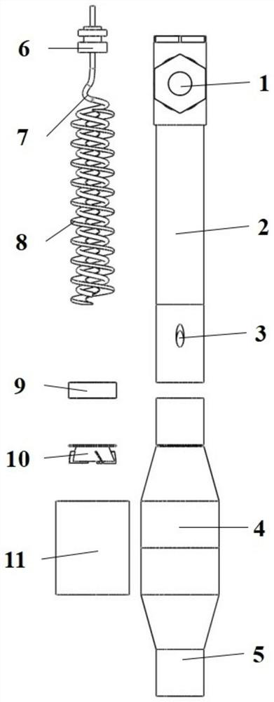
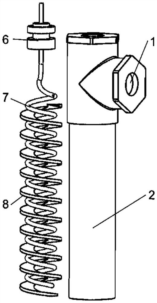
[0030] A low-temperature plasma cooperative SCR exhaust gas treatment device, including a low-temperature plasma module and an SCR reaction module, the low-temperature plasma module includes an air intake pipe 1 and a low-temperature plasma generation pipe 2, and the air intake pipe 1 is arranged on the low-temperature plasma generation pipe 2 The upper end of the SCR reaction module includes a urea injection pipe 3, an SCR reaction housing 4, and an exhaust pipe 5. The input end of the urea injection pipe 3 is connected to the low-temperature plasma generation pipe 2, and the output end is connected to the SCR reaction housing 4. , the exhaust pipe 5 is arranged at the end ...


PUM


Abstract

The invention discloses a low-temperature plasma synergistic SCR waste gas treatment device which comprises a plasma module consisting of a low-temperature plasma generating tube, a spiral high-voltage electrode, a spiral guide vane and insulating ceramic, and an SCR reaction module consisting of a urea injection tube, a mixer, a guide device, an SCR reaction shell and a catalyst. According to the scheme of the low-temperature plasma synergistic SCR waste gas treatment device, when waste gas enters the low-temperature plasma generation pipe from the gas inlet pipe, passes through the spiral guide vanes and uniformly flows in the discharge area, the spiral high-voltage electrode and the spiral guide vanes improve the circulation and uniformity of gas, and the discharge reaction space is effectively utilized, and the reaction waste gas and the sprayed urea are fully mixed through the mixer and the fluid director and quickly react in the SCR reactor. The low-temperature plasma technology and the SCR technology are organically combined, PM and NOX are integrally treated, and the device has the advantages of being simple, capable of saving energy, high in purification efficiency and the like.

Description

technical field [0001] The invention relates to the technical field of waste gas treatment research, in particular to a low-temperature plasma cooperative SCR waste gas treatment device. Background technique [0002] With the continuous development of the globalization of the world economy, the shipping industry plays an increasingly important role in the development of the world economy. Among the gas pollutants produced by marine diesel engines, in addition to carbon dioxide (CO 2 ), also includes a large amount of sulfur oxides (SO X ), nitrogen oxides (NO X ), particulate matter (PM), etc., causing serious harm to the environment and human health. The regulations on ship emissions in various countries are becoming increasingly stringent, so many exhaust gas treatment technologies have emerged as the times require. [0003] The pre-treatment technology mainly uses low-sulfur fuel or clean energy to reduce exhaust pollutant emissions, but the cost is too high. [0004]...

Claims


Application Information

Patent Timeline
IPC IPC(8): B01D53/32B01D53/86B01D53/56
CPCB01D53/32B01D53/8631B01D53/8696B01D2259/818
Inventor 陈宁陈再仁房鹏翔侯宇周逸龙干羽
Owner JIANGSU UNIV OF SCI & TECH
Learn More