Supercharge Your Innovation With Domain-Expert AI Agents!

Method for recycling industrial low-temperature heat energy and externally-hung heat pump system

A heat pump system, plug-in technology, applied in the direction of heat pumps, lighting and heating equipment, refrigeration components, etc., can solve the problems of energy-saving and emission-reduction upgrading and transformation of unsuitable process equipment, low-temperature heat energy is not recycled, and engineering implementation is difficult, etc., to achieve Reduce corrosion resistance requirements and safety risks, reduce consumption, and have strong versatility

Pending Publication Date: 2021-08-13
吴嘉
View PDF0 Cites 0 Cited by
  • Summary
  • Abstract
  • Description
  • Claims
  • Application Information

AI Technical Summary

Problems solved by technology

[0005] In view of this, the purpose of the present invention is to solve the problem that a large amount of low-temperature heat energy in industrial production equipment is not recycled, and the existing heat energy recovery technology is not suitable for the upgrading and transformation of energy saving and emission reduction of completed process equipment, and the problem of difficulty in project implementation is provided. A method for recovering industrial low-temperature heat energy and an external heat pump system

Method used


Image

  • Method for recycling industrial low-temperature heat energy and externally-hung heat pump system
  • Method for recycling industrial low-temperature heat energy and externally-hung heat pump system
  • Method for recycling industrial low-temperature heat energy and externally-hung heat pump system

Examples


Embodiment 1

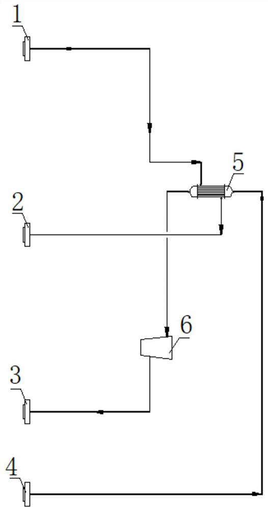
[0044] see Figure 5 In this embodiment, on the basis of the comparative example, an external heat pump system is installed outside the process device. In this embodiment, the process stream is refined methanol, the heat pump working fluid is water, and the booster equipment uses a compressor.

[0045] From the pipeline between the top of the atmospheric column 1-3 and the atmospheric column condenser 1-16, the refined methanol vapor is drawn out through the pipeline, and connected to the external heat pump system through the first process stream inlet 2-5. The inlet 2-5 of a process stream is connected with the first heat pump compressor 2-1, and the refined methanol vapor enters the first partition heat exchanger 2-2 after being compressed and boosted by the first heat pump compressor 2-1, and is mixed with liquid water Carry out heat exchange, transfer heat energy to water and return to the process device from the first process stream outlet 2-6, and enter the original subs...

Embodiment 2

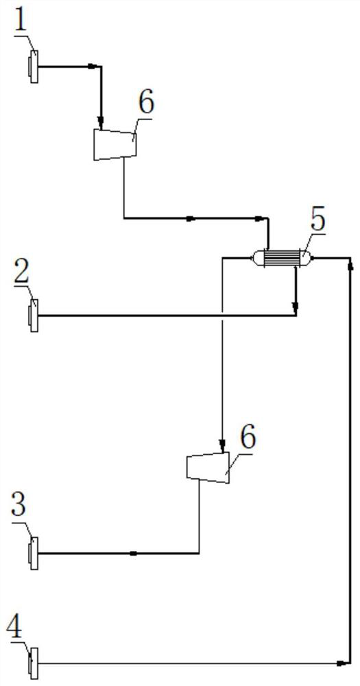
[0048] see Image 6 , this embodiment is further optimized on the basis of Embodiment 1, the difference is that: the external heat pump system has increased the second partition heat exchanger 2-3, the second process stream inlet 2-7, the second process stream Outlet 2-8; wherein, the first partition heat exchanger 2-2 is connected in parallel with the second partition heat exchanger 2-3, and the heat pump working fluid inlet 4 is connected with the first partition heat exchanger 2-2 and the second partition respectively. The partition heat exchanger 2-3 is connected, and the liquid water introduced from the heat pump working fluid inlet 4 performs heat exchange in the first partition heat exchanger 2-2 and the second partition heat exchanger 2-3 respectively, and is transformed into Water vapor, the two streams of water vapor merge and enter the second heat pump compressor 2-4 for compression and boosting, and then transported to the process device through the heat pump worki...


PUM


Abstract

The invention belongs to the technical field of industrial production energy recovery, and relates to a method for recycling industrial low-temperature heat energy and an externally-hung heat pump system. The externally-hung heat pump system is arranged outside a process device, a process stream in the process device is conveyed into the externally-hung heat pump system and exchanges heat with a heat pump working medium arranged in the externally-hung heat pump system, and the heat pump working medium absorbing the heat energy is conveyed into the process device to replace an original heating working medium to supply heat to the process device. The externally-hung heat pump system comprises a process stream inlet, a process stream outlet, a heat pump working medium inlet, a heat pump working medium outlet, a dividing wall type heat exchanger and boosting equipment used for increasing the pressure of the process stream or the heat pump working medium. The externally-hung heat pump system and the process device are connected only through a pipeline, and original spatial arrangement and process flow do not need to be changed; and waste heat in the process device is absorbed by the heat pump working medium, and the heat pump working medium replaces the original heating working medium, so that the consumption of the original heating working medium is reduced.

Description

technical field [0001] The invention belongs to the technical field of industrial production energy recovery, and relates to a method for recovering industrial low-temperature heat energy and an external heat pump system. Background technique [0002] In traditional industrial production devices, there is a large amount of low-temperature heat energy that is not recovered and reused for engineering heating. Instead, it uses cooling methods to dissipate this part of heat energy into nature, resulting in a waste of energy resources. A typical example is the rectification process in chemical production: the vapor phase material from the top of the rectification tower is usually cooled by circulating water to condense and cool it down, not only does not recycle the latent heat of condensation and sensible heat of cooling of the material, It also consumes additional operating energy and water resources of the cooling system. [0003] Among the technical innovations disclosed in ...

Claims


Application Information

Patent Timeline
Patent Type & Authority Applications(China)
IPC IPC(8): F25B30/06
CPCF25B30/06
Inventor 吴嘉鲍艳
Owner 吴嘉
Features
  • R&D
  • Intellectual Property
  • Life Sciences
  • Materials
  • Tech Scout
  • Unparalleled Data Quality
  • Higher Quality Content
  • 60% Fewer Hallucinations
Learn More