Two-stage interception type scrap isolation type motor shaft polishing machine based on intermediary principle

A motor shaft and isolated technology, which is applied in the direction of surface polishing machine tools, grinding/polishing equipment, grinding/polishing safety devices, etc. Problems affecting the polishing effect of the motor shaft

Active Publication Date: 2021-08-17
XUZHOU FANGDA MOTOR CO LTD
View PDF11 Cites 2 Cited by
  • Summary
  • Abstract
  • Description
  • Claims
  • Application Information

AI Technical Summary

Problems solved by technology

[0003] At present, the polishing of the surface of the motor shaft is generally carried out manually with a polishing machine. The arc of the surface of the motor shaft produced by this polishing method cannot be well guaranteed, which affects the polishing quality of the motor shaft, and the motor The shaft needs to be pinched by the staff during polishing. During the polishing process, the friction between the motor shaft and the sandpaper produces high temperature and is easy to burn hands. At the same time, the cooling of the motor shaft after polishing is not easy to deal with. The current technology usually uses flowing water to wash the motor shaft. But it will obviously waste a lot of precious water resources; the existing motor shaft will produce splash debris during polishing, and some debris will adhere to the surface of the motor shaft, and some high-speed splash debris is likely to hurt How to automatically collect or remove these debris from the eyes of the staff is a technical problem; in addition, the motor shaft will generate noise during polishing, which will damage the hearing of the staff and affect the working mood of the staff
[0004] The patent application with the publication number CN107813214A discloses a polishing device for a motor shaft. The base is provided with a left positioning block and a right positioning block; the left positioning block and the right positioning block are respectively provided with a left positioning hole and a right positioning hole, and The above two positioning holes are located on the same axis line; one side of the left positioning block is provided with a motor on the motor base; one side of the motor shaft is provided with a left cylindrical block located in the left positioning hole, and the left cylindrical block is opened There are accommodation slots; there is a fixed cylinder in the right positioning hole, and the inner diameter of the fixed cylinder is the same as the diameter of the motor shaft; the materials of the left cylindrical block and the fixed cylinder are electromagnets; there is a telescopic cylinder on the side of the right positioning block; There is an electromagnet block located in the fixed cylinder; a slidable substrate is provided between the left positioning block and the right positioning block; a polishing component that can be lifted up and down is installed on the substrate. This patent can realize the automatic operation of the entire polishing process, avoiding Manual hand-held motor shaft is used for polishing, which saves labor and improves polishing efficiency and polishing quality. However, the problem of high surface temperature after polishing of the motor shaft cannot be solved during use, and the dust generated during polishing cannot be automatically collected or removed. Splashing debris and some debris adhering to the surface of the motor shaft will not be able to reduce the noise generated during polishing to a certain extent, thus affecting the polishing effect of the motor shaft

Method used


Image

  • Two-stage interception type scrap isolation type motor shaft polishing machine based on intermediary principle
  • Two-stage interception type scrap isolation type motor shaft polishing machine based on intermediary principle
  • Two-stage interception type scrap isolation type motor shaft polishing machine based on intermediary principle

Examples


Embodiment Construction

[0037] The technical solutions in the embodiments of the present invention will be clearly and completely described below in conjunction with the accompanying drawings in the embodiments of the present invention. Obviously, the described embodiments are only some of the embodiments of the present invention, not all of them; based on The embodiments of the present invention and all other embodiments obtained by persons of ordinary skill in the art without making creative efforts belong to the protection scope of the present invention.

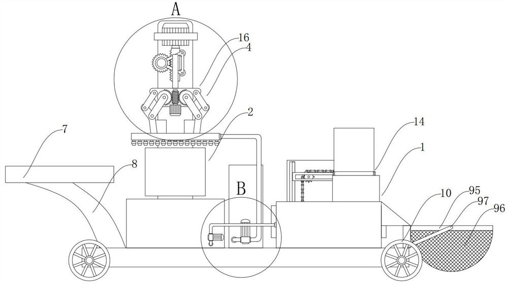
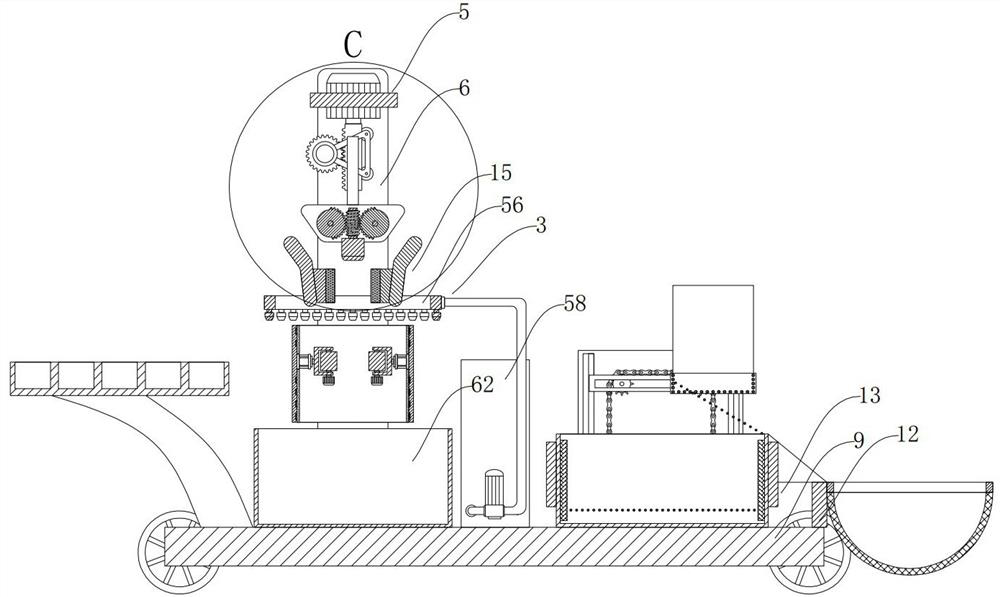
[0038] Such as figure 1 , 2 As shown, the present invention is based on the intermediary principle of the two-stage interception type debris isolation type motor shaft polishing machine, which consists of a polishing rotation auxiliary unit 5, an interactive cooling collection integration unit 1, a split water curtain intervention noise weakening protection unit 3, and a motor Shaft limit unit 4, motor shaft placement frame 7, motor shaft suppo...


PUM


Abstract

The invention discloses a two-stage interception type scrap isolation type motor shaft polishing machine based on an intermediary principle. The machine is composed of a segmentation type water curtain intervention noise weakening protection unit, an interaction type cooling and collecting integrated unit, a polishing rotation auxiliary unit, a motor shaft limiting unit, a motor shaft containing frame, a polishing supporting vertical plate, a bottom moving platform, a motor shaft supporting crank arm, a collecting auxiliary vertical plate, moving wheels and a motor shaft collecting supporting base. The invention belongs to the technical field of motor shaft machining machinery, and particularly relates to a two-stage interception type scrap isolation type motor shaft polishing machine based on an intermediary principle. Under the condition that no scrap collecting equipment or cooling equipment or other related sensors are involved, the interaction type cooling and collecting integrated unit is arranged, the cooling function on a motor shaft is creatively achieved, meanwhile, residual scraps attached to the motor shaft are removed and collected, and the technical problem difficult to solve that in the prior art, the motor shaft is driven to move underwater is solved.

Description

technical field [0001] The invention belongs to the technical field of motor shaft processing machinery, and specifically refers to a two-stage interception debris isolation type motor shaft polishing machine based on the intermediary principle. Background technique [0002] A motor is a device that converts electrical energy into mechanical energy. It uses energized coils (that is, stator windings) to generate a rotating magnetic field and acts on the rotor (such as a squirrel-cage closed aluminum frame) to form a magneto-electric power rotation torque. Motors are divided into DC motors and AC motors according to the power used. Most of the motors in the power system are AC motors, which can be synchronous motors or asynchronous motors (the motor stator magnetic field speed and rotor rotation speed do not maintain synchronous speed). The motor is mainly composed of a stator and a rotor. The direction of the current-carrying wire in the magnetic field is related to the dire...

Claims


Application Information

Patent Timeline
Patent Type & Authority Applications(China)
IPC IPC(8): B24B29/04B24B55/02B24B55/06B24B41/06B24B27/00B24B41/00B24B41/02
CPCB24B27/0007B24B29/04B24B41/005B24B41/02B24B41/06B24B55/02B24B55/06
Inventor 李运田
Owner XUZHOU FANGDA MOTOR CO LTD
Why Eureka
Try Eureka