Optical composite film assembling machine of backlight module

An optical composite film and backlight module technology, which is applied in metal processing and other directions, can solve the problems of affecting display imaging, inconsistent size of backlight module, and inability to meet assembly requirements, etc.

Active Publication Date: 2021-08-17
深圳市橙信科技有限公司
View PDF4 Cites 2 Cited by
  • Summary
  • Abstract
  • Description
  • Claims
  • Application Information

AI Technical Summary

Problems solved by technology

[0002] The backlight module is one of the pipe parts of the liquid crystal display panel. The backlight module is the main part of the liquid crystal backlight module display; the surface of the backlight module is pasted with multi-layer optical films. The backlight module assembly on the existing market is mainly Paste different optical films on the backlight module layer by layer; and the optical films have been cut into shape before bonding, and the size of the LCD screens currently on the market ranges from a few inches to dozens of inches. The size of the backlight module is inconsistent, which cannot meet the assembly requirements of existing products of different sizes; if the optical film is not tightly pressed or the dust removal effect is not good during the pressing process, it will affect the imaging of the display

Method used


Image

  • Optical composite film assembling machine of backlight module
  • Optical composite film assembling machine of backlight module
  • Optical composite film assembling machine of backlight module

Examples


Embodiment 1

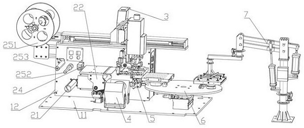
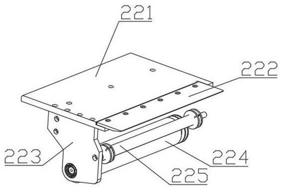
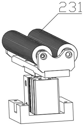
[0036] Embodiment 1: as figure 1 As shown, an optical composite film assembly machine for a backlight module is provided with a workbench, unwinding and unwinding tension components, a cutting and pressing machine 3, an ion fan 4, a CCD detector 5, a rotary pressing station 6 and a manipulator 7. The workbench is provided with a bottom surface 11 and a square box 12, and the square box is installed on the left side of the bottom surface; the winding and unwinding tension assembly is provided with a discharge device 21, a cutting table 22, and an adjustment roller assembly 23. Horizontal splint 24 and winding device; the cutting table is provided with a table top 221, a cutter 222, a bracket 223, a dust removal drum 224 and a discharge adjustment drum 225; the adjustment drum group is provided with an adjustment drum 231 and a cylinder, A layer of sticky paper is attached to the surface of the dust removal drum 224; the winding device is provided with a winder 251, a transition...

Embodiment 2

[0037] Embodiment 2: as figure 2 As shown, there is a cutter on the cutting table. When the type of optical composite film used is an optical composite film that has been cut and formed and pasted on the base film, the optical composite film will be cut when it slides over the cutter. The knife can separate the optical composite film from the base film; when using the optical composite film that needs to be cut, the optical composite film is cut by the cutting and pressing device. The optical composite film assembly machine of the backlight module can be applied to various Types of optical composite films.

Embodiment 3

[0038] Embodiment 3: as figure 2 with image 3As shown, in order to ensure the cleanliness of the optical composite film and avoid the assembly failure caused by the sticking of sundries on the optical composite film, an adjustment roller assembly, a dust removal roller and an ion fan are set up; When the film passes under the dust removal roller, the roller assembly is adjusted to rise, so that the optical composite film and the dust removal roller are closely bonded, and the dust removal roller performs a dust removal on the optical composite film; after the optical composite film is cut and transferred to the pressing station, it passes above the ion fan , The ion fan can eliminate the static electricity on the surface of the optical composite film, prevent static electricity from adsorbing dust and other sundries in the air on the optical composite film, and the electrostatic fan can perform secondary dust removal on the optical composite film.


PUM


Abstract

The invention discloses an optical composite film assembling machine of a backlight module. The optical composite film assembling machine is provided with a workbench, a winding and unwinding tension assembly, a cutting and pressing machine, an ion fan, a CCD detector, a rotary pressing station and a mechanical arm, wherein the workbench is provided with a square box and a bottom face, and the square box is installed on the left side of the bottom face; the winding and unwinding tension assembly is installed on the workbench; a cutting and pressing machine is mounted on the square box; the ion fan is mounted on the bottom surface, and the rotary pressing station is mounted on the bottom surface; the ion fan is located between the winding and unwinding tension assembly and the rotary pressing station; the CCD detector is installed on the right side of the square box and located in front of the winding and unwinding tension assembly; and the mechanical arm is positioned in front of the rotary pressing station. Automatic control over liquid crystal screen film pasting operation can be achieved, and the liquid crystal screen film pasting efficiency can be improved to a large extent.

Description

technical field [0001] The invention relates to the field of backlight modules and backlight sources, in particular to the field of assembly of backlight modules. Background technique [0002] The backlight module is one of the pipe parts of the liquid crystal display panel. The backlight module is the main part of the liquid crystal backlight module display; the surface of the backlight module is pasted with multi-layer optical films. The backlight module assembly on the existing market is mainly Paste different optical films on the backlight module layer by layer; and the optical films have been cut into shape before bonding, and the size of the LCD screens currently on the market ranges from a few inches to dozens of inches. The size of the backlight module is inconsistent, which cannot meet the assembly requirements of existing products of different sizes; if the optical film is not tightly pressed or the dust removal effect is not good during the pressing process, it wi...

Claims


Application Information

Patent Timeline
Patent Type & Authority Applications(China)
IPC IPC(8): B29C65/56B29C65/00B26D1/02
CPCB29C65/56B29C66/41B29C66/814B26D1/025
Inventor 伍永莲
Owner 深圳市橙信科技有限公司
Why Eureka
Try Eureka