
Multi-axis robot dot-matrix reinforcing steel bar bundling system and working method thereof

A multi-axis robot, dot matrix technology, applied in manufacturing computing systems, bundling machinery parts, comprehensive factory control, etc. high degree of effect

Active Publication Date: 2021-08-17
济客筑科技太仓有限公司
View PDF9 Cites 7 Cited by
  • Summary
  • Abstract
  • Description
  • Claims
  • Application Information

AI Technical Summary

Problems solved by technology

[0010] Purpose of the invention: In order to overcome the above deficiencies, the purpose of the present invention is to provide a dot-matrix steel bar binding system of a multi-axis robot, which solves the problem of the need for large-area steel bar binding operations in the prior art. Binding or using a hand-held steel binding machine for binding requires a lot of waste of manpower, resulting in a waste of labor resources.

Method used


Image

  • Multi-axis robot dot-matrix reinforcing steel bar bundling system and working method thereof
  • Multi-axis robot dot-matrix reinforcing steel bar bundling system and working method thereof
  • Multi-axis robot dot-matrix reinforcing steel bar bundling system and working method thereof

Examples


Embodiment 1

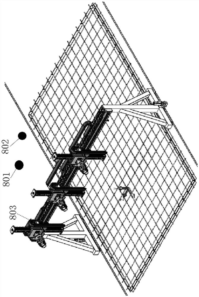
[0075] Such as figure 1 The shown multi-axis robot dot matrix steel bar binding system includes a visual recognition camera 801, a visual positioning camera 802, a multi-axis binding robot 803 and a control system. The visual recognition camera 801 and the visual positioning camera 802 are arranged on a truss or a On the shaft strapping robot 803, the visual recognition camera 801, the visual positioning camera 802 and the multi-axis strapping robot 803 are all connected to the control system;

[0076] The visual recognition camera 801 obtains the global data of the required bundled steel mesh, generates the bundled node process document through the image processing module of the control system, and then the control system plans the bundled path through the path planning module, that is, recognizes the two-dimensional coordinates, that is, the XY coordinates , forming the intersection point data of the horizontal and vertical steel mesh sheets;

[0077] The visual positioning...

Embodiment 2

[0102] Such as Figure 5 , 6 The multi-axis binding robot 803 shown includes an X-axis moving assembly 1, at least one Y-axis moving assembly 2, at least one Z-axis moving assembly 3 and at least one steel bar binding machine 4, and the at least one Y-axis moving assembly 2 is arranged on On the X-axis moving assembly 1, the X-axis moving assembly 1 can drive at least one Y-axis moving assembly 2 to move along the X-axis horizontal direction, the at least one Y-axis moving assembly 2, at least one Z-axis moving assembly 3 and at least one The steel bar binding machines 4 are provided in one-to-one correspondence. The Z-axis moving assembly 3 is arranged on the Y-axis moving assembly 2. The Y-axis moving assembly 2 can drive the Z-axis moving assembly 3 to move along the Y-axis horizontal direction. The steel bar binding The machine 4 is arranged on the Z-axis moving assembly 3, and the Z-axis moving assembly 3 can drive the steel bar binding machine 4 to move along the Z-axis...


PUM


Abstract

The invention discloses a multi-axis robot dot-matrix reinforcing steel bar bundling system and a working method thereof. The system comprises a visual identification camera, a visual positioning camera, a multi-axis bundling robot and a control system, wherein the visual identification camera acquires global data of reinforcing steel bar meshes needing to be bundled, and cross intersection data of transverse and longitudinal reinforcing steel bar meshes are formed; the visual positioning camera acquires position information of all cross intersections on the transverse and longitudinal reinforcing steel bar meshes in a vertical direction; and the multi-axis bundling robot conducts reinforcing steel bar bundling according to a planned bundling path. According to the multi-axis bundling robot dot-matrix reinforcing steel bar bundling system, three-dimensional coordinates of a target bundling point and a rotation angle of a bundling gun are calculated by means of a motion control algorithm and then sent to a motion controller in sequence, and the bundling gun is moved to a position above the bundling point for bundling. The working method is simple and easy to implement, the automation degree of a working process is high, the needed manpower is less, the production efficiency is improved, and the method is suitable for industrial large-scale application.

Description

technical field [0001] The invention belongs to the technical field of advanced manufacturing and automation, and in particular relates to a dot-matrix steel bar binding system of a multi-axis robot. The invention also relates to a working method of a dot-matrix steel bar binding system of a multi-axis robot. Background technique [0002] At present, most of the steel bar binding in the industry is done manually with the help of ordinary tools or semi-automatic tools, and the work efficiency depends on the proficiency of the workers and the number of personnel; a few factories use welded steel mesh instead of part of the steel bar binding, but it cannot solve the binding of truss bars ; Some domestic enterprises use articulated arm steel bar binding robots, which have a high degree of freedom and strong adaptability, but the cost is high and the operating area is limited, so it cannot provide multiple binding points and independent binding at the same time; the walking robot...

Claims


Application Information

Patent Timeline
Patent Type & Authority Applications(China)
IPC IPC(8): B65B13/18B65B27/10B65B57/14
CPCB65B13/18B65B27/10B65B57/14Y02P90/30
Inventor 樊留群李显双董兴涛潘虎吴杰陈炜邓剑楠
Owner 济客筑科技太仓有限公司
Learn More