Bridge type thermal rectifier
A thermal rectifier and bridge technology, applied in the field of bridge thermal rectifiers, to achieve the effect of improving energy conversion efficiency
- Summary
- Abstract
- Description
- Claims
- Application Information
AI Technical Summary
Problems solved by technology
Method used
Image

Examples
Embodiment Construction
[0023] The technical solution of the present disclosure will be described in detail below in conjunction with the accompanying drawings. In the description of the present invention, it should be understood that the terms "first", "second", "third" and "fourth" are used for descriptive purposes only, and should not be understood as indicating or implying relative importance or implicitly The number of technical features indicated is used only to distinguish the different components.
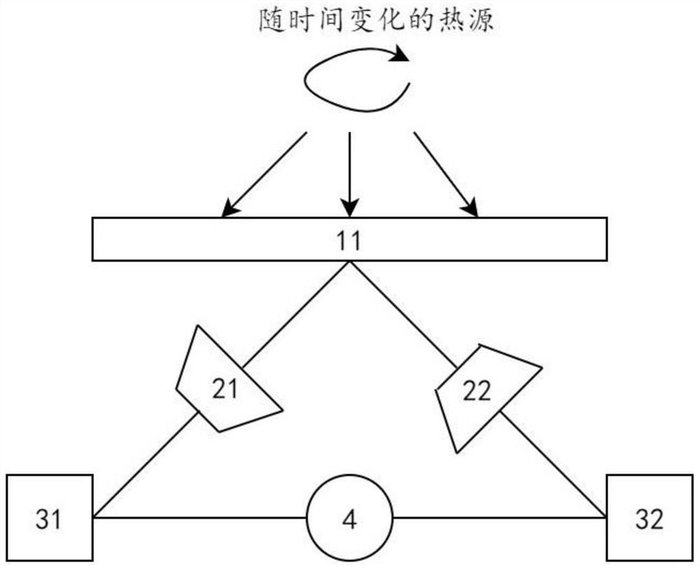
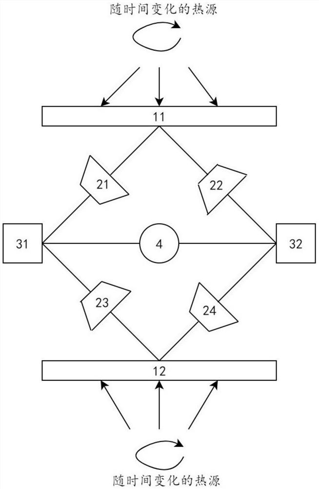
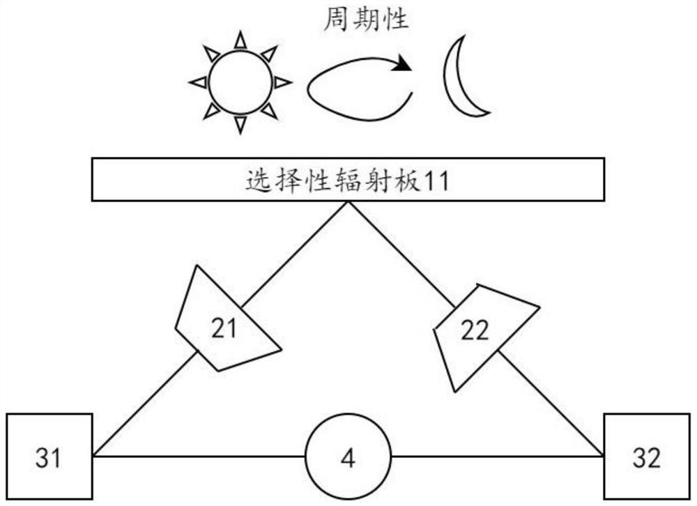
[0024] In addition, the working mechanism of the thermal diode involved in the present invention is: when the direction of the external temperature difference is consistent with the bias direction of the thermal diode, the thermal resistance of the thermal diode is extremely small, which is defined as R Fwd. , the heat flow can quickly transfer from the hot side to the cold side through the thermal diode. When the external temperature difference direction is opposite to the bias direction of the t...
PUM
 Abstract
Description
Claims
Application Information
 - R&D
- Intellectual Property
- Life Sciences
- Materials
- Tech Scout
- Unparalleled Data Quality
- Higher Quality Content
- 60% Fewer Hallucinations
Browse by: Latest US Patents, China's latest patents, Technical Efficacy Thesaurus, Application Domain, Technology Topic, Popular Technical Reports.
© 2025 PatSnap. All rights reserved.Legal|Privacy policy|Modern Slavery Act Transparency Statement|Sitemap|About US| Contact US: help@patsnap.com