Eureka AIR delivers breakthrough ideas for toughest innovation challenges, trusted by R&D personnel around the world.

Electric furnace flue gas primary dust removal and waste heat recovery system without water cooling flue

A waste heat recovery system and flue technology, applied in the field of industrial flue gas treatment, can solve the problems of consumption, a large amount of high-temperature flue gas heat is not recycled, large electric energy and water, etc., to save water resources, facilitate cleaning, and improve treatment. effect of ability

Inactive Publication Date: 2021-08-20
李庆波
View PDF0 Cites 0 Cited by
  • Summary
  • Abstract
  • Description
  • Claims
  • Application Information

AI Technical Summary

Problems solved by technology

This method achieves the purpose of flue gas cooling and dust removal, but the above method has the following disadvantages: on the one hand, it consumes a lot of electricity and water, and on the other hand, the heat of a large amount of high-temperature flue gas has not been recycled.

Method used


Image

  • Electric furnace flue gas primary dust removal and waste heat recovery system without water cooling flue
  • Electric furnace flue gas primary dust removal and waste heat recovery system without water cooling flue
  • Electric furnace flue gas primary dust removal and waste heat recovery system without water cooling flue

Examples


Embodiment

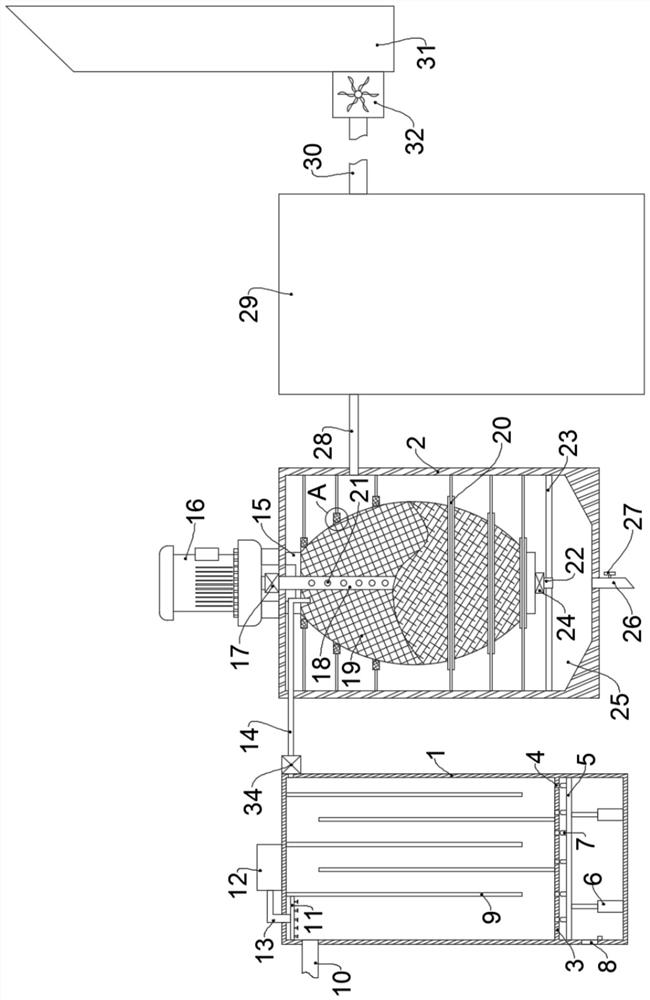
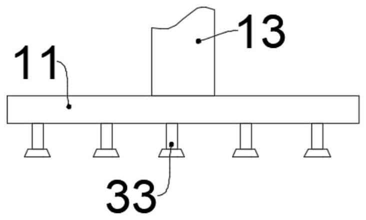
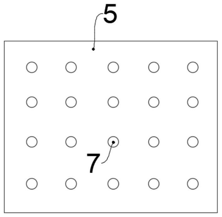
[0030] Such as Figure 1-5 As shown, a primary dust removal and waste heat recovery system for electric furnace flue gas without a water-cooled flue includes a primary treatment box 1, and the right side of the primary treatment box 1 is provided with a dust removal air duct 14 for transmitting electric furnace flue gas. The air duct 14 is provided with a temperature control valve 34 that can be opened and closed according to the temperature control near the position of the primary treatment box 1. The other end of the dust removal air duct 14 is provided with a secondary treatment box 2, and the inside of the secondary treatment box 2 is provided with a The dust removal filter bag 19 for removing dust particles, the ring side of the dust removal filter bag 19 is provided with a plurality of limit rings 20 arranged in parallel, the dust removal filter bag 19 is connected with the limit ring 20, and the middle part of the dust removal filter bag 19 is provided with a The jet pi...


PUM


Abstract

The invention belongs to the technical field of industrial flue gas treatment, and particularly relates to an electric furnace flue gas primary dust removal and waste heat recovery system without a water-cooling flue. The system comprises a primary treatment box, a dust removal gas guide pipe is arranged on the right side of the primary treatment box, a temperature control valve is arranged at the position, close to the primary treatment box, of the dust removal gas guide pipe, a secondary treatment box is arranged at the other end of the dust removal gas guide pipe, a dust removal filter bag is arranged in the secondary treatment box, a plurality of parallel limiting rings are arranged on the annular side of the dust removal filter bag, a gas spraying pipe is arranged in the middle of the dust removal filter bag, a fixing frame fixedly connected to the bottom of the secondary treatment box is arranged at the upper end of the dust removal filter bag, an air pump is arranged at the upper end, penetrating through the fixing frame and the secondary treatment box, of the air spraying pipe, an electromagnetic pulse valve is arranged at the position, close to the air pump, of the air spraying pipe, and a dust falling pipe is arranged at the lower end of the dust removal filter bag. Water cooling is not needed for flue gas treatment, and meanwhile waste heat recovery can be conducted on electric furnace flue gas.

Description

technical field [0001] The invention belongs to the technical field of industrial flue gas treatment, and in particular relates to a primary dust removal and waste heat recovery system for electric furnace flue gas without a water-cooled flue. Background technique [0002] The iron and steel industry is a major player in environmental pollution and energy consumption. Flue gas dust removal and waste heat recovery are one of the countermeasures for the iron and steel industry to protect the environment and save energy. The electric furnace produces a large amount of dust-laden high-temperature flue gas during the production process. The average amount of dust generated per ton of steel is 18-20kg, and the heat taken away with the flue gas is about 150M, which seriously wastes energy and pollutes the environment. [0003] At present, the domestic flue gas cooling method is mainly water-cooled, that is, the primary flue gas generated by smelting is extracted from the fourth hol...

Claims


Application Information

Patent Timeline
Patent Type & Authority Applications(China)
IPC IPC(8): F27D17/00F23G7/06B01D50/00B01D46/02B01D46/04
CPCF27D17/008F27D17/004F23G7/06B01D46/02B01D46/04F27D2017/006B01D50/20Y02P10/25
Inventor 李庆波
Owner 李庆波
Why Eureka
Eureka Blog
Learn More