Composite material plate shell with thickness gradual change area and forming device and method of composite material plate shell

A composite material plate and molding device technology, which is applied in transportation and packaging, space navigation equipment, space navigation aircraft, etc. The effect of improving the production quality and improving the emission effect

Active Publication Date: 2021-08-24
SHANGHAI COMPOSITES SCI & TECH CO LTD
View PDF7 Cites 1 Cited by
  • Summary
  • Abstract
  • Description
  • Claims
  • Application Information

AI Technical Summary

Problems solved by technology

[0003] Through the search of existing patent documents, it is found that the invention patent of CN112123810A discloses a process method for improving the internal molding quality of a large-thickness composite material rudder. Wrinkle defects caused by hot press forming of wall thickness products, but not suitable for large plate and shell products formed by hot autoclave

Method used


Image

  • Composite material plate shell with thickness gradual change area and forming device and method of composite material plate shell
  • Composite material plate shell with thickness gradual change area and forming device and method of composite material plate shell
  • Composite material plate shell with thickness gradual change area and forming device and method of composite material plate shell

Examples


Embodiment 1

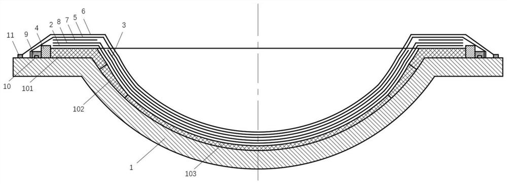
[0036] The invention provides a molding device for a composite material shell with a thickness gradient zone, such as Figure 1-2 As shown, it is especially suitable for forming devices with single-curved or double-curved plate and shell structures with flange edges, including forming mold 1, breathable release cloth 2, porous isolation film 3, surrounding strip 4, air felt 5 And vacuum film 6. The forming mold 1 is used as a basic load-bearing part, and the composite material prepreg forming the plate shell is laid on the inner surface of the forming mold 1 to form a composite material layer. The shape of the molding die 1 is designed according to the shape of the plate and shell to be produced, for example, the typical structure includes a hemispherical shape with an outer platform, a truncated cone shape, and the like. The surrounding bar 4 is movably installed on the outer edge platform of the inner surface of the forming mold 1, and one side of the surrounding bar 4 is u...

Embodiment 2

[0040]This embodiment 2 is formed on the basis of embodiment 1. Through the design of the pressure stabilizing structural parts and the adsorption structural parts, the pressure area applied to the composite material layer during the manufacturing process of the plate and shell is made uniform, and the loss of the composite material layer is ensured. Within the control range, the manufacturing quality of the plate shell is improved.

[0041] Such as Figure 1-2 As shown, a rubber-absorbing felt 8 with adsorption function is set in the composite material plate and shell forming device, and the rubber-absorbing felt 8 is arranged between the air-permeable release cloth 2 and the porous isolation film 3 for adsorption on the pressurized and heated composite Composite material spilled during material layers. By designing the adsorption capacity of the rubber-absorbing felt 8, that is, by designing the rated adsorption capacity of the rubber-absorbing felt 8, it is ensured that th...

Embodiment 3

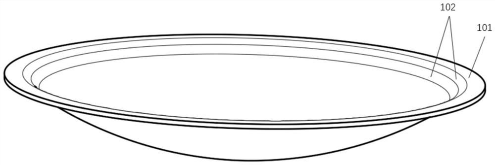
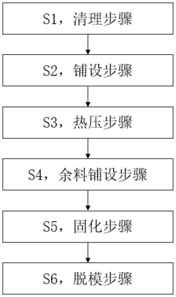
[0044] This embodiment 3 is a forming method for a composite material plate and shell with a thickness gradient zone formed by using the molding device for a composite material plate and shell with a thickness gradient zone in embodiment 1 or embodiment 2, such as Figure 1-3 As shown, taking a composite material panel shell with large wall thickness, including a hyperboloid surface, and variable thickness as an example, the main part of the composite material panel shell 100 to be manufactured is spherical (double curvature surface), and the outer edge of the main body is set Plane flange, the flange and the adjacent part of the spherical surface are the thickened area 101, and its main part is called the flat thick area 103, and the distance from the thickened area 101 to the flat thick area 103 whose thickness gradually becomes thinner is recorded as the thickness gradient area 102. The thickening zone 101 has a wall thickness of 12 mm, the flat thickness zone has a wall th...


PUM

PropertyMeasurementUnit
thicknessaaaaaaaaaa
thicknessaaaaaaaaaa

Abstract

The invention relates to a composite material plate shell with a thickness gradual change area and a forming device and method of the composite material plate shell in the technical field of composite material forming. The forming device comprises a forming mold, breathable demolding cloth, a porous isolation film, an enclosing strip, breathable felt and a vacuum film. Prepreg is laid between the breathable demolding cloth and the inner surface of the forming mold, the breathable demolding cloth, the porous isolation film, the breathable felt and the vacuum film are sequentially stacked on the prepreg, the side face of the enclosing strip is in make contact with the end face of a composite material layer, and the enclosing strip is used for preventing the composite material layer from flowing outwards. The breathable demolding cloth, the porous isolation film and the enclosing strip are arranged in the breathable felt in a covering mode, the vacuum film is arranged outside the breathable felt in a covering mode, and the vacuum film is in sealed connection with the surface of the forming mold. Through the design of a pressure stabilization structural part and an adsorption structural part, a pressure area applied to the composite material layer in the plate shell manufacturing process is uniform, it is guaranteed that the loss amount of the composite material layer is within a control range, and the plate shell manufacturing quality is improved.

Description

technical field [0001] The invention relates to the technical field of composite material forming, and in particular relates to a composite material plate shell with a thickness gradient area and a forming device and method thereof. Background technique [0002] At present, a large number of high-strength composite materials are used in the load-bearing structures of aerospace launch vehicles, satellites and space vehicles. The main advantage of composite materials is that composite materials have a good weight reduction effect and can increase the payload of a single launch. In order to improve the structural strength and load-bearing efficiency, the load-bearing parts of composite plate and shell are generally provided with a large wall thickness thickening area at the position where the internal stress is relatively large, and the continuous and smooth transition of the wall thickness from thick to thin is realized through the wall thickness gradient area. . When the pre...

Claims


Application Information

Patent Timeline
Patent Type & Authority Applications(China)
IPC IPC(8): B29C70/34B29C70/54B64G1/22
CPCB29C70/342B29C70/54B64G1/22Y02T50/40
Inventor 徐云研沈辉鲁东东赵丁丁魏耀林史文锋邱保强夏海祥张国凯张志斌侯小龙余娜
Owner SHANGHAI COMPOSITES SCI & TECH CO LTD
Why Eureka
Try Eureka