Cremator flue gas pipeline system

A technology for cremation furnaces and flue gas pipes, which is applied in the direction of exhaust gas exhaust devices, climate sustainability, and reduction of greenhouse gases. problems, to achieve the effect of improving heat utilization efficiency, low construction cost, and reasonable overall layout

Pending Publication Date: 2021-08-24
杨万明
View PDF0 Cites 0 Cited by
  • Summary
  • Abstract
  • Description
  • Claims
  • Application Information

AI Technical Summary

Problems solved by technology

Most of the traditional cremation furnaces use air extraction equipment to directly absorb the external air into the furnace to supply oxygen. The external cold air and the high temperature of the furnace form a certain temperature difference. When the cold air enters the furnace, the fire will become smaller and affect the combustion of the corpse. efficiency
[0005] In recent years, cremation furnaces in some areas have been optimized in the air supply link. For example, the high-temperature flue gas generated by the cremation furnace is used to initially heat the combustion-supporting air to improve combustion efficiency; however, a large amount of remaining heat in the flue gas will still be consumed Directly discharged to the outside or consumed in the flue gas purification process, the heat of the flue gas is not fully utilized
However, if a heat exchange device is installed in the flue gas purification link, on the one hand, it will be inconvenient for actual on-site installation and application, and on the other hand, the utilization efficiency is not ideal

Method used


Image

  • Cremator flue gas pipeline system
  • Cremator flue gas pipeline system
  • Cremator flue gas pipeline system

Examples


Embodiment 1

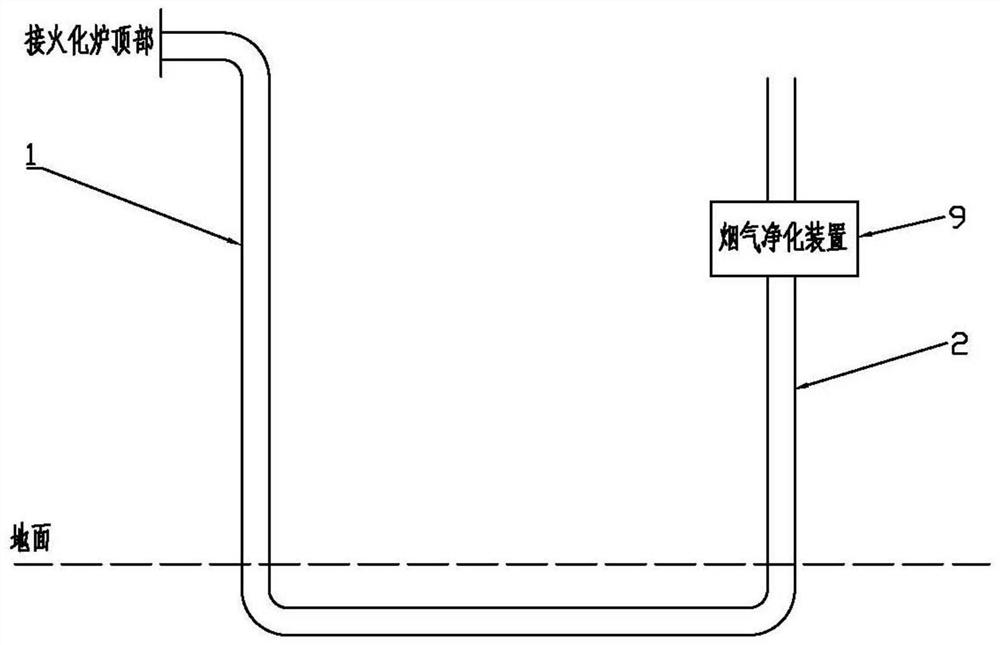
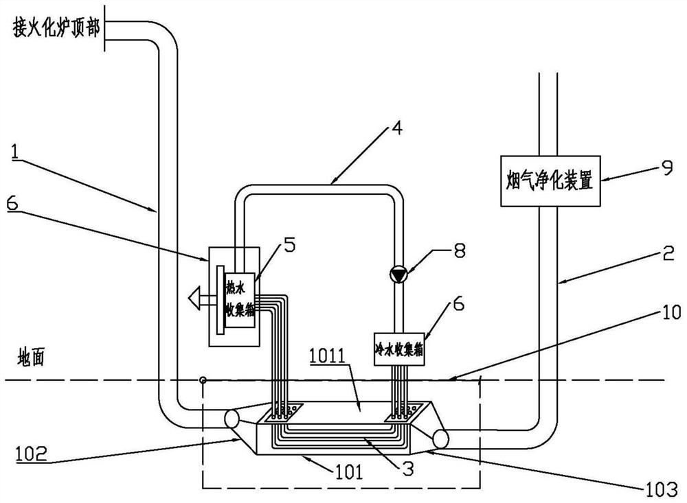
[0038] Such as figure 2 As shown, a flue gas pipeline system of a cremation furnace includes a flue gas transfer pipe 1 and a flue gas discharge pipe 2. At the entrance of the gas discharge pipe 2, a flue gas purification device 9 is arranged on the flue gas discharge pipe 2; part of the pipe section of the flue gas transfer pipe is buried underground, which is recorded as a horizontal flue;

[0039] The horizontal flue is sequentially divided into a front bend, an integrated flue 101 and a rear bend, wherein the integrated flue is the main part of the horizontal flue (the length ratio is usually more than 70%);

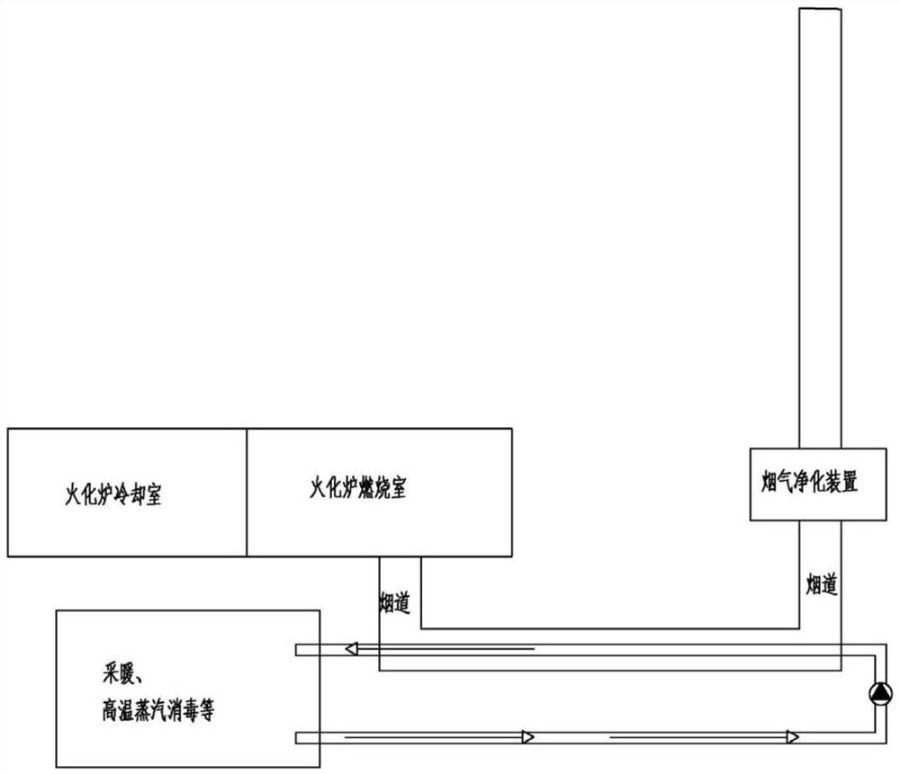
[0040] The feature of this embodiment is that it also includes a heat exchange medium circulation pipeline and a heat exchanger 7; the heat exchanger 7 is a well-known and mature product in the field of heat supply technology, and can be selected according to needs.

[0041] The heat exchange medium circulation pipeline includes an integrated heat exchange pipe 3 a...

Embodiment 2

[0053] Based on the above embodiments, a spare horizontal pipe can also be fixedly arranged on the side of the integrated flue 101 and equipped with a corresponding pipe joint assembly.

[0054] In this way, when it is necessary to repair the integrated flue and the integrated heat exchange tube, it can be temporarily switched to the standby horizontal tube to continue transporting the flue gas, so that the machine will not be shut down for a long time. In addition, the pipe diameter of the spare horizontal pipe can be consistent with the pipe diameters of the above-mentioned front-end bend pipe and rear-end bend pipe, which is convenient for quick and reliable sealing and docking.

Embodiment 3

[0056] With reference to the principle of any of the above embodiments, a parallel system of multiple cremation furnace heat exchange systems can also be formed, that is, there are multiple cremation furnaces, and correspondingly, there are multiple groups of flue gas transfer pipes, flue gas discharge pipes, and heat exchange medium circulation. Pipelines; the corresponding hot water collection tanks on each group of heat exchange medium circulation pipelines are connected to each other, or a unified hot water collection tank and heat exchanger are arranged on multiple sets of heat exchange medium circulation pipelines.

[0057] In this way, the intensive management of the entire site can be realized, and the efficiency of thermal energy utilization can be further improved.


PUM


Abstract

The invention discloses a cremator flue gas pipeline system. The problem that in the prior art, waste heat of high-temperature flue gas generated by cremators is insufficiently utilized is solved. In the cremator flue gas pipeline system, a horizontal flue is sequentially divided into a front-end bent pipe, an integrated flue and a rear-end bent pipe, wherein the integrated flue is a body part of the horizontal flue. Integrated heat exchange pipes (a constituent part of heat exchange medium circulating pipelines) are installed at the integrated flue to absorb heat of the flue gas generated by the cremators, the front ends and the rear ends of the integrated heat exchange pipes upwards extend out of the ground correspondingly to communicate with the two ends of water return pipes, hot water collecting boxes and cold water collecting boxes are arranged at the communicating positions correspondingly, and circulating water pumps are arranged on the water return pipes to realize circulating heat exchange. The high-temperature flue gas of the cremators is efficiently recycled, the economical efficiency of the cremators is improved, the transformation and construction cost is low, the overall layout is more reasonable, and meanwhile the requirement for material selection of devices of flue gas purification devices is lowered.

Description

technical field [0001] The invention relates to a system for utilizing waste heat of flue gas, in particular to a cremation furnace flue gas piping system. Background technique [0002] Cremation is a method of disposing of corpses, specifically burning the corpses into ashes with torches. The equipment of the crematorium includes cremation furnaces, corpse trucks, ash picking trucks and subsequent equipment for environmental protection. [0003] Cremation furnace refers to the equipment used to cremate the remains. Due to the particularity of the industry and environmental protection requirements, usually the top of the cremation furnace is connected to the vertical pipe through the elbow pipe to the underground, and then connected to the vertical flue gas discharge pipe through the horizontal pipe buried in the ground. The flue gas purification device ensures the cleanliness of the tail gas discharged into the air from the cremation furnace through purification treatment....

Claims


Application Information

Patent Timeline
Patent Type & Authority Applications(China)
IPC IPC(8): F23G1/00F23J11/02F23J15/06
CPCF23G1/00F23J11/02F23J15/06Y02E20/30
Inventor 杨万明
Owner 杨万明
Why Eureka
Try Eureka