Cooling liquid and machining chip separating and recycling device for machine tool

A technology for separation, recovery, and cooling liquid, applied in metal processing equipment, metal processing machinery parts, manufacturing tools, etc., can solve problems such as increasing production costs, and achieve the effects of reducing production costs, large irradiation area, and good sterilization effect.

Inactive Publication Date: 2021-08-27
绩溪县诚信机械有限公司
View PDF0 Cites 0 Cited by
  • Summary
  • Abstract
  • Description
  • Claims
  • Application Information

AI Technical Summary

Problems solved by technology

[0003] When the machine tool uses the tool to process the workpiece, a large amount of cutting coolant is required to continuously cool the tool to avoid high heat generated during processing and affect the machining accuracy. The coolant in the prior art will be discharged directly after one use, improving reduce the production cost, for this reason, the present invention proposes a kind of machine tool coolant and machining debris separation and recovery device that can solve the above problems

Method used


Image

  • Cooling liquid and machining chip separating and recycling device for machine tool
  • Cooling liquid and machining chip separating and recycling device for machine tool
  • Cooling liquid and machining chip separating and recycling device for machine tool

Examples


Embodiment 1

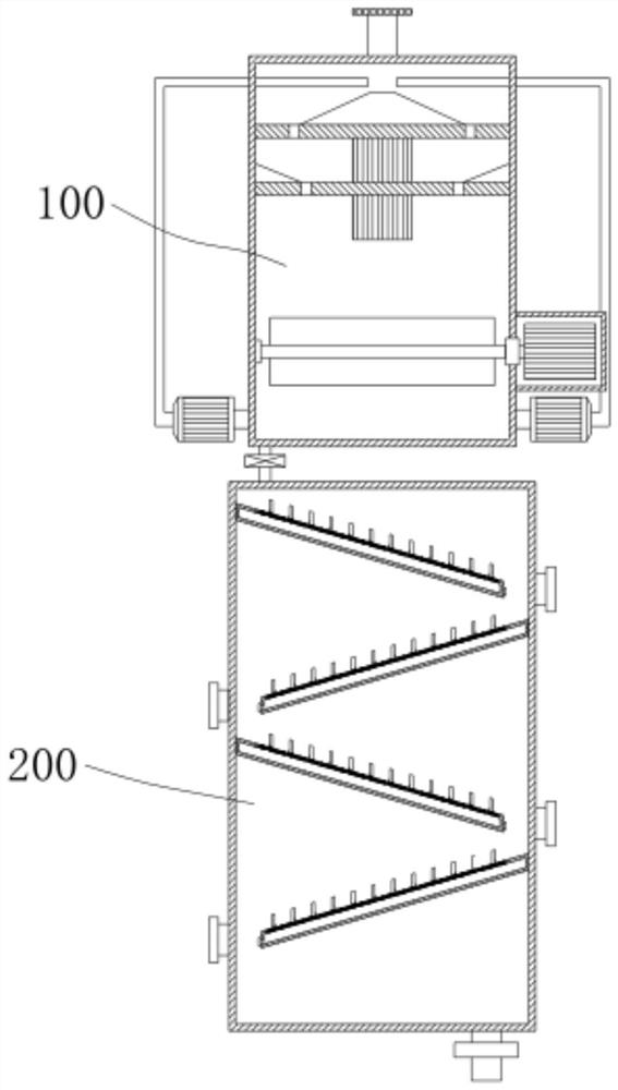
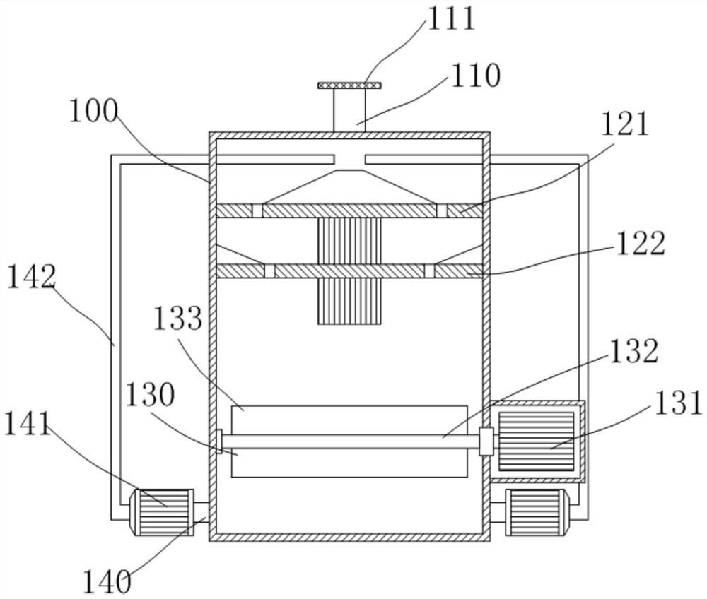
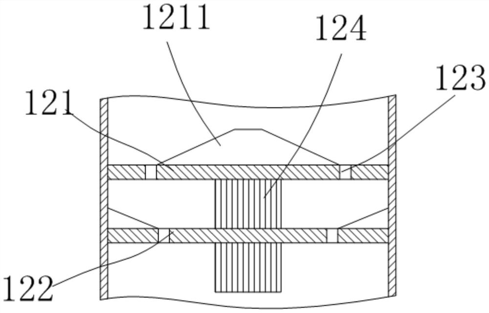
[0031]The present invention provides a technical solution: a machine tool coolant and processing debris separation and recovery device, including a liquid inlet box 100, the upper end of the liquid inlet box 100 is provided with a liquid inlet 110, and a foreign matter filter is movably installed on the liquid inlet 110 111, a first liquid receiving pan 121 and a second liquid receiving pan 122 are vertically spaced in the liquid inlet tank 100, and are connected to the inner wall of the liquid inlet tank 100, and a tapered block 1211 is arranged in the middle of the upper end of the first liquid receiving pan 121, The conical block 1211 corresponds to the liquid inlet 110, the first liquid receiving tray 121 and the second liquid receiving tray 122 are respectively provided with a liquid drop ring groove 123, and the first liquid receiving tray 121 and the second liquid receiving tray 122 are respectively provided with a drop ring groove 123. The array is provided with several...

Embodiment 2

[0035] Cooling mechanism 130 comprises rotating shaft 132, stirring rod, cooling plate 133 and motor 131, rotating shaft 132 is arranged in the liquid inlet box 100, and rotating shaft 132 is provided with several groups of stirring rods, and each group of stirring is provided with cooling plate 133, cooling The plate 133 has a cavity, and a cooling copper pipe is arranged in the cavity, and a motor 131 is fixedly installed at the lower end of the liquid inlet tank 100, and the output shaft of the motor 131 is drivingly connected to the rotating shaft 132;

[0036] There are infusion ports 140 on both sides of the bottom of the liquid inlet tank 100. A pump body 141 is installed outside the infusion port 140. The output end of the pump body 141 is connected to a liquid return pipe 142. The liquid return pipe 142 extends upward, and the liquid return pipe 142 passes through the liquid inlet. The tank 100 is above the first tapered block 1211 .

[0037] Specifically, the coolant...

Embodiment 3

[0039] The first run-off plate 231 and the second run-off plate 232 are all made up of an upper plate 233 and a lower plate 234, and the upper plate 233 and the lower plate 234 form a frame-shaped plate with a cavity through the connecting plate 235, and the upper plate 233 collects scrap There is a gap below the groove, and the upper plate 233 is provided with a lower side groove 2331 on one side of the gap, and the upper layer plate 233 is provided with an upper side groove 2332 on the other side of the gap, and a material receiving plate 2333 is movable in the lower side groove 2331. The plate 2333 extends into the upper groove 2332, the lower groove 2331 is provided with a spring set 2334, one end of the spring set 2334 is connected to the inner wall of the lower groove 2331, and the other end is connected to the receiving plate 2333;

[0040] The liquid blocking plate 237 is provided with a pushing block 238 on the side close to the gap, the pushing block 238 has an inclin...


PUM


Abstract

The invention discloses a cooling liquid and machining chip separating and recycling device for a machine tool. The cooling liquid and machining chip separating and recycling device comprises a liquid inlet box and a filtrate box, wherein a liquid inlet is formed in the upper end of the liquid inlet box; a foreign matter filtering net is movably mounted at the liquid inlet; a first liquid receiving disc and a second liquid receiving disc are arranged vertically in the liquid inlet box at intervals and are connected to the inner walls of the liquid inlet box; a conical block is arranged in the middle of the upper end of the first liquid receiving disc and corresponds to the liquid inlet and is opposite to the liquid inlet; liquid dropping circular grooves are separately formed in the first liquid receiving disc and the second liquid receiving disc; multiple groups of ultraviolet lamps are arranged separately under the first liquid receiving disc and the second liquid receiving disc; the liquid inlet box is provided with a cooling mechanism under the second liquid receiving disc; the filtrate box is arranged under the liquid inlet box and is connected with the liquid inlet box through a liquid delivery pipe; a liquid delivery controlling valve is mounted on the liquid delivery pipe; a runoff mechanism is arranged in the filtrate box; and the runoff mechanism comprises a first runoff plate and a second runoff. According to the cooling liquid and machining chip separating and recycling device disclosed by the invention, recycling of the cooling liquid can be realized, and the production cost is reduced.

Description

technical field [0001] The invention relates to the technical field of coolant recovery, in particular to a device for separating and recovering machine tool coolant and machining debris. Background technique [0002] A machine tool refers to a machine that manufactures a machine, also known as a machine tool or a tool machine, and is customarily referred to as a machine tool. Generally divided into metal cutting machine tools, forging machine tools and woodworking machine tools. There are many ways to process mechanical parts in modern machinery manufacturing: in addition to cutting, there are also casting, forging, welding, stamping, extrusion, etc. The final machining is done by cutting on the machine tool. Machine tools play an important role in the modernization of the national economy. [0003] When the machine tool uses the tool to process the workpiece, a large amount of cutting coolant is required to continuously cool the tool to avoid high heat generated during ...

Claims


Application Information

Patent Timeline
Patent Type & Authority Applications(China)
IPC IPC(8): B23Q11/10
CPCB23Q11/1069
Inventor 章晓明
Owner 绩溪县诚信机械有限公司
Why Eureka
Try Eureka