
Chip circuit function verification system, method, equipment and storage medium

A circuit function and verification system technology, which is applied in the fields of electrical digital data processing, computer-aided design, special data processing applications, etc., can solve the problems of heavy manual workload, deviation of software application scenarios, and long verification work cycle, etc., to promote Realize, improve time efficiency and avoid waste of human resources

Active Publication Date: 2021-08-27
北京燧原智能科技有限公司
View PDF5 Cites 15 Cited by
  • Summary
  • Abstract
  • Description
  • Claims
  • Application Information

AI Technical Summary

Problems solved by technology

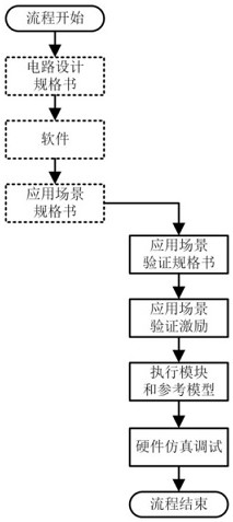
[0004] However, the method provided in the above-mentioned prior art has the following defects: First, the verification work cannot be carried out before the specification of the application scenario is completed, resulting in insufficient mobilization of the human resources of the verification personnel
Secondly, verifiers need to collect and understand scenario information and manually write verification incentives based on the scenario information, resulting in a long verification cycle and a large manual workload
At the same time, when the verifier understands the application scenario specification, due to the complexity of the application scenario information, it is easy to cause the written verification incentives to deviate from the software application scenario
In summary, the chip circuit function verification method provided by the existing technology is difficult to realize the verification of large-scale application scenarios

Method used


Image

  • Chip circuit function verification system, method, equipment and storage medium
  • Chip circuit function verification system, method, equipment and storage medium
  • Chip circuit function verification system, method, equipment and storage medium

Examples


Embodiment 1

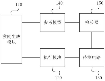
[0036] image 3 It is a schematic diagram of a chip circuit function verification system provided in Embodiment 1 of the present invention. The chip circuit function verification system provided in this embodiment is applicable to the situation of verifying the function of a chip circuit based on the application environment, and can be implemented by software and / or It can be realized by means of hardware, for example, it can include using Verilog language, VHDL (Veri-High-Speed ​​Integrate Circuit Hardware Description Language, ultra-high-speed integrated circuit hardware description language), or a circuit netlist that can be used for simulation generated after compiling the two , Verilog codes or VHDL codes written in other languages, circuit netlists written in other languages ​​with Verilog codes or VHDL codes as intermediate products, etc., can also be hardware circuits implemented based on hardware description languages ​​or netlists.

[0037] Correspondingly, such as ...

Embodiment 2

[0064] Figure 5 It is a schematic diagram of a chip circuit function verification system provided by Embodiment 2 of the present invention. Such as Figure 5 As shown, on the basis of the above-mentioned embodiments, this embodiment specifies the internal structure of the incentive generating module, further refines the incentive generating module 110 into a software simulator 1101 and an automation script 1102, and the software simulator 1101 and the automation script 1102 Script 1102 communication connection.

[0065] Among them, the software simulator 1101 is used to generate chip software simulation results according to the software scene instructions and instruction flow format files, and input the instruction flow data in the chip software simulation results to the automation script 1102 .

[0066] Specifically, the software scenario instruction may be an instruction in a software application scenario of the circuit under test 130 . The instruction stream format file...

Embodiment 3

[0098] Figure 11 It is a flowchart of a chip circuit function verification method provided by Embodiment 3 of the present invention. This embodiment is applicable to the situation where the function of the chip circuit is verified based on the application environment. The method can be implemented by the chip circuit function provided by the embodiment of the present invention. verification system, which can be implemented by software and / or hardware. Correspondingly, such as Figure 11 As shown, the method includes the following operations:

[0099] S310. Obtain chip software simulation results through the stimulus generation module, generate target verification stimulus according to the chip software simulation result, and input the target verification stimulus to the execution module and the reference model.

[0100] S320. Perform parameter configuration of the circuit under test according to the target verification stimulus through the execution module, and generate a t...


PUM


Abstract

The embodiment of the invention discloses a chip circuit function verification system, a method, equipment and a storage medium. The system comprises an excitation generation module, an execution module, a to-be-tested circuit, a reference model and a tester, the excitation generation module obtains a chip software simulation result, generates target verification excitation and inputs the target verification excitation to the execution module and the reference model; the execution module performs parameter configuration on the to-be-tested circuit according to the target verification excitation, generates a target excitation signal and inputs the target excitation signal to the to-be-tested circuit; the to-be-tested circuit generates a test output result according to the parameter configuration result and the target excitation signal; the reference model generates a reference output result according to the target verification excitation simulation; and the tester matches the test output result with the reference output result to obtain a function verification result of the circuit to be tested. According to the system of the invention, the time efficiency, the resource utilization rate and the accuracy of chip circuit function verification can be improved, and the realization of large-scale application scene verification is promoted.

Description

technical field [0001] The embodiments of the present invention relate to the field of chip technology, and in particular to a chip circuit function verification system, method, device and storage medium. Background technique [0002] In chip design, functional verification of chip integrated circuits in software application scenarios can test the core functions of chips in the early stage of circuit development, which is an essential link to ensure the success of chip design. With the emergence and development of ultra-large-scale chips such as 5G and artificial intelligence, the testing scale of chips in software application scenarios is becoming larger and more complex. [0003] figure 1 It is a schematic flow chart of a chip circuit function verification method in the prior art, figure 2 It is a schematic diagram of resources required for each stage of chip circuit function verification in the prior art, wherein the dotted box corresponds to the non-hardware circuit v...

Claims


Application Information

Patent Timeline
IPC IPC(8): G06F30/398
CPCG06F30/398
Inventor 杨兵毕金琼郑晓萌李春红帅晋李振
Owner 北京燧原智能科技有限公司
Learn More