Eureka AIR delivers breakthrough ideas for toughest innovation challenges, trusted by R&D personnel around the world.

Anti-cavitation device and construction method for hydraulic structures

A technology for hydraulic structures and construction methods, applied in construction, protection devices, water conservancy projects, etc., can solve the problems of unavoidable cavitation damage, aggravated cavitation and cavitation, and prone to cracking, etc. The effect of low construction difficulty and easy batch processing and production

Active Publication Date: 2022-06-07
CHINA THREE GORGES CORPORATION +1
View PDF10 Cites 0 Cited by
  • Summary
  • Abstract
  • Description
  • Claims
  • Application Information

AI Technical Summary

Problems solved by technology

One way of thinking is to add some special materials to the concrete to improve the anti-abrasion effect, such as the scheme recorded in the Chinese patent document CN100396638C, a concrete additive and its preparation method and concrete using the additive, although this scheme can improve the cavitation resistance effect , but it is still difficult to avoid cavitation damage, and different concrete materials are prone to cracking
[0003] The inventor intends to install anti-cavitation panels at flow-through locations where cavitation and cavitation problems are prone to occur, but it is also a difficult construction problem to make the anti-cavitation panels arranged in arrays flat
Uneven anti-cavitation panels can exacerbate cavitation and cavitation problems

Method used


Image

  • Anti-cavitation device and construction method for hydraulic structures
  • Anti-cavitation device and construction method for hydraulic structures
  • Anti-cavitation device and construction method for hydraulic structures

Examples


Embodiment 1

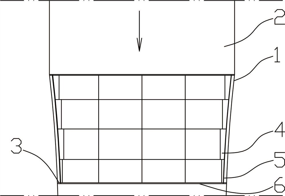
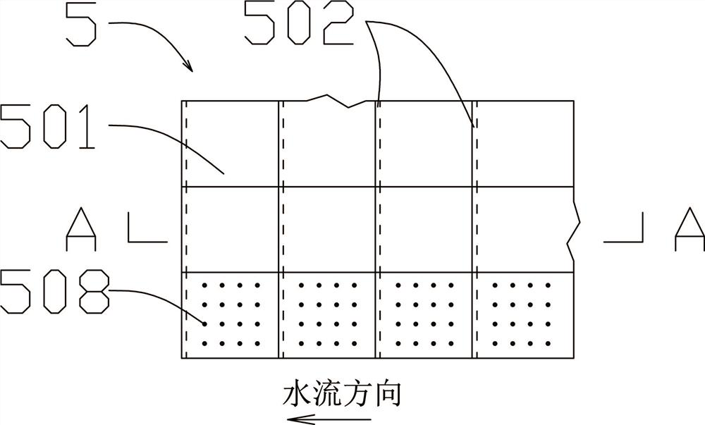
[0037] as Figure 1 、 3 , 4, a hydraulic building air defense erosion device, air defense corrosion device 5 includes a fixed frame 504 embedded in concrete, fixed frame 504 is connected to the bearing layer 506, air defense erosion panel 501 is fixedly connected to the bearing layer 506. Thus the structure, so that the air defense erosion panel 501 is reliably fixed to the inner wall of the hydraulic tunnel 2, to alleviate the cavitation damage at this location.

[0038] Preferred schemes such as Figure 4 In, the air defense corrosion panel 501 is a cavitation-resistant alloy material, including a stainless steel material or titanium alloy material. When the overcurrent flow rate is less than 14m / s. For example, when the overcurrent flow rate is 8m / s, a smooth and flat defect-free cavitation-resistant alloy material is used, and a titanium alloy material is preferred in this example. The bearing layer 506 adopts a polymer material with certain elasticity. For example, ultra-high m...

Embodiment 2

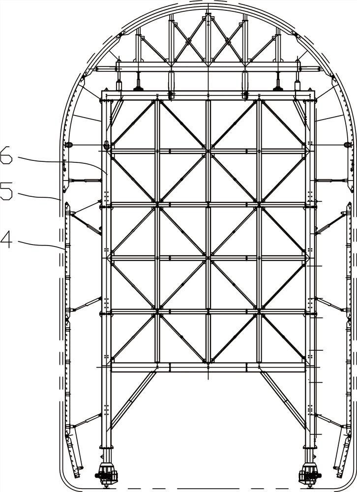
[0048] as Figure 1 、 2 , one of the above-described construction methods of the hydraulic building anti-aircraft erosion device, comprising the following steps:

[0049] S1, in the variable section section 1 select a single lining trolley 6, the lining trolley 6 according to the preset hydraulic tunnel 2 inner wall contour shape of the template 4 vertical mold;

[0050]S2, in the lining trolley 6 template paste double-sided adhesive, the air-defense corrosion device 501 of the air-defense erosion device 501 through the double-sided adhesive bonding connection; In the preferred embodiment, when installing the anti-aircraft corrosion device 5, a steel wire is buried in the double-sided adhesive, and the steel wire is arranged along the axis direction of the variable section section 1, for cutting the double-sided adhesive with steel wire when dismantling the mold, so as to facilitate the removal of the mold.

[0051] S3, the fixed frame 504 of the anti-corrosion device 5 is fixed by...

experiment example 1

[0061] On the overcurrent section side of the variable section section 1 with an overcurrent flow rate of 8m / s, as the experimental side, the air defense corrosion device 5 arranged in the array is installed, the air defense corrosion panel 501 adopts titanium alloy material, and the bearing layer 506 adopts a polymer material with certain elasticity; On the other side is the original overcurrent section of concrete with a certain roughness, which acts as the control side. Hydrophones and high-speed cameras are used to monitor the vaping of the nascent and development of cavitation on both sides, respectively, such as Figure 6 As shown in , when cavitation is detected on the control side, no cavitation occurs on the experimental side.


PUM

PropertyMeasurementUnit
elastic modulusaaaaaaaaaa

Abstract

The invention provides a hydraulic structure anti-cavitation device and a construction method. The anti-cavitation device includes a fixed frame pre-buried in concrete, the fixed frame is connected to a bearing layer, and the anti-cavitation panel is fixedly connected to the bearing layer. The anti-cavitation panel is an anti-cavitation alloy material, including stainless steel or titanium alloy. Or the anti-cavitation panel is made of rubber material. Paste double-sided tape on the template of the lining trolley, and connect the anti-cavitation erosion panel of the anti-cavitation device to the template through double-sided adhesive tape; connect the next lining trolley to the current lining trolley, and repeat the above steps , install the end formwork, pour concrete, and vibrate the concrete compactly; after the concrete curing reaches the age, the formwork is removed; through the above steps, the construction of the anti-cavitation device in the variable section section is realized. By using a special anti-cavitation panel on the flow-through part that is prone to cavitation damage, the possibility of cavitation can be reduced and cavitation damage can be minimized when cavitation occurs.

Description

Technical field [0001] The present invention relates to the field of hydraulic tunnel air defense erosion, in particular a hydraulic building air defense corrosion device and construction method. Background [0002] In a flowing liquid, for some reason the pressure of the local area suddenly drops below the vapor pressure corresponding to the temperature of the liquid in this area, part of the liquid evaporates, the gas dissolved in the liquid escapes, and a process of cavitation bubbles is formed in the liquid flow, called cavitation. When the cavitation bubble enters the higher pressure area with the liquid flow, the sudden change of external conditions causes the cavitation bubble to collapse, and the liquid movement around the original cavitation bubble suddenly increases the pressure in the local area. If the liquid flow continues to form, growing cavitation bubble in the solid wall near the frequent collapse, the wall will suffer from the repeated impact of huge pressure, a...

Claims


Application Information

Patent Timeline
Patent Type & Authority Patents(China)
IPC IPC(8): E02D31/06E02D29/063E02D29/07
CPCE02D31/06E02D29/063E02D29/07E02D2300/0001E02D2300/0026E02D2300/0029E02D2300/0035E02D2300/0006E02D2600/20E02D2300/002E02D2250/0007Y02E10/20
Inventor 翟俨伟杨正贵熊建武李新明杨小华李健薄
Owner CHINA THREE GORGES CORPORATION
Why Eureka
Eureka Blog
Learn More