
Multi-stage variable-temperature cold and heat source Stirling cold and power co-production system

A technology of combined cooling and power generation and Stirling engine, applied in refrigerators, refrigeration components, refrigeration and liquefaction, etc., can solve the problem of large temperature difference between liquefied natural gas and heat exchanger, limited combustion heat of the engine, and increased irreversible heat exchange loss etc. to achieve the effects of reducing parameter sensitivity, compact structure, and reducing irreversible losses in heat transfer

Pending Publication Date: 2021-08-31
TECHNICAL INST OF PHYSICS & CHEMISTRY - CHINESE ACAD OF SCI
View PDF5 Cites 0 Cited by
  • Summary
  • Abstract
  • Description
  • Claims
  • Application Information

AI Technical Summary

Problems solved by technology

However, the phase modulation capability of the motor in this system is limited, and the compression chamber requires a large volume to achieve efficient coupling between the engine and the refrigerator, and the system performance is sensitive to parameters such as damping, so the performance of the whole machine is severely limited
Secondly, in the practical application of gas liquefaction, on the one hand, the combustion heat absorbed by the engine is relatively limited, and the flue gas still carries a large amount of high-temperature waste heat; At present, the existing heat-driven cogeneration system architecture regards the heat exchange between the Stirling engine and the refrigerator as an isothermal process. The temperature difference leads to the increase of irreversible heat transfer loss, which restricts the improvement of system performance

Method used


Image

  • Multi-stage variable-temperature cold and heat source Stirling cold and power co-production system
  • Multi-stage variable-temperature cold and heat source Stirling cold and power co-production system
  • Multi-stage variable-temperature cold and heat source Stirling cold and power co-production system

Examples


Embodiment Construction

[0037] The following description serves to disclose the present invention to enable those skilled in the art to carry out the present invention. The preferred embodiments described below are only examples, and those skilled in the art can devise other obvious variations. The basic principles of the present invention defined in the following description can be applied to other embodiments, variations, improvements, equivalents and other technical solutions without departing from the spirit and scope of the present invention.

[0038] Those skilled in the art should understand that, in the disclosure of the present invention, the terms "vertical", "transverse", "upper", "lower", "front", "rear", "left", "right", The orientations or positional relationships indicated by "vertical", "horizontal", "top", "bottom", "inner", "outer", etc. are based on the orientation or positional relationship shown in the drawings, which are only for the convenience of describing the present inventi...


PUM


Abstract

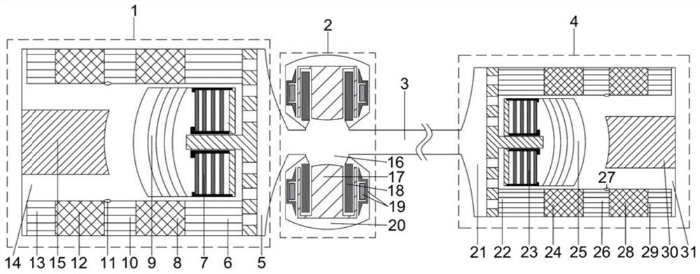
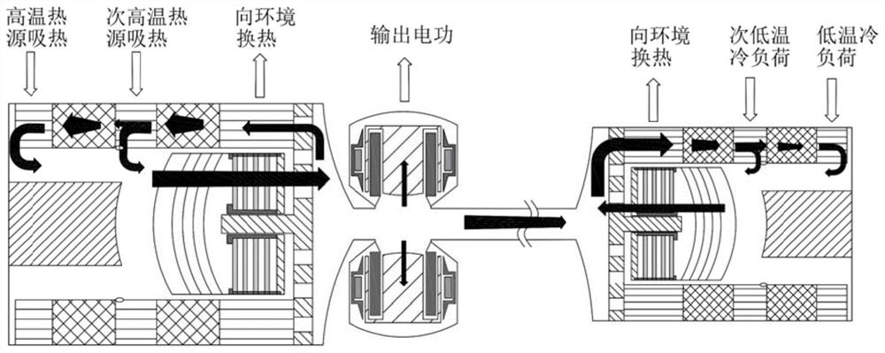
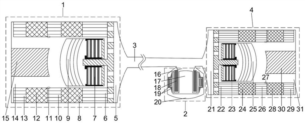
The invention relates to a multi-stage variable-temperature cold and heat source Stirling cold and power co-production system. The system comprises a multi-stage free piston Stirling engine, a multi-stage free piston Stirling cryocooler, an acoustic resonance tube connected with the multi-stage free piston Stirling engine and the multi-stage free piston Stirling cryocooler, and a linear motor arranged on the acoustic resonance tube. According to the system, the multi-stage free piston Stirling engine and the multi-stage free piston Stirling cryocooler are adopted, irreversible heat exchange loss of a heat exchanger, a cold source and a heat source can be greatly reduced, the system efficiency is improved, and through the mode that the multi-stage free piston Stirling engine and the multi-stage free piston Stirling cryocooler are coupled through the acoustic resonance tube, parameter sensitivity can be reduced, moving parts can be reduced, the reliability of the co-production system can be improved, in addition, a heat source and the multi-stage free piston Stirling cryocooler are effectively isolated through the acoustic resonance tube, and the safety of the co-production system can be improved.

Description

technical field [0001] The invention relates to the technical field of cogeneration of cold and power, in particular to a multi-stage variable temperature cold and heat source Stirling cogeneration system for cold and power. Background technique [0002] Thermally driven combined cooling and power devices have good application prospects in special occasions where electric energy is scarce. For example, it is applied to the exploitation and transportation of unconventional natural gas such as coalbed methane and shale gas. These gas sources are usually scattered, and there are many remote trenches. It is difficult to meet the conditions for large-scale oil and gas fields to be exploited. The system can not only burn part of the natural gas to liquefy most of the remaining gas, but also obtain part of the electric energy for the control system and small power loads. [0003] The Chinese invention patent (201910229901.0) proposes a cogeneration system based on a free-piston St...

Claims


Application Information

Patent Timeline
IPC IPC(8): F02G1/043F02G1/055F02G1/057F25B9/14F25B49/02
CPCF02G1/043F02G1/055F02G1/057F25B9/14F25B49/02Y02E20/14
Inventor 余国瑶孙浩杰戴巍马英罗二仓
Owner TECHNICAL INST OF PHYSICS & CHEMISTRY - CHINESE ACAD OF SCI
Learn More