
High-temperature gas heat pump system with mechanical supercooling function

A gas heat pump, high temperature technology, applied in heat pumps, mechanical equipment, refrigerators, etc., can solve problems such as power consumption, large irreversible loss of heat exchange, and inability to ensure the uniformity of temperature difference fields.

Pending Publication Date: 2021-05-18
上海航天工业(集团)有限公司 +2
View PDF0 Cites 0 Cited by
  • Summary
  • Abstract
  • Description
  • Claims
  • Application Information

AI Technical Summary

Problems solved by technology

Existing gas heat pump systems usually use a single engine to drive a single compressor. For a single-stage heat pump system, an excessively high pre-valve temperature will cause significant throttling losses and reduce the energy efficiency of the system, thereby reducing the primary energy utilization efficiency of the gas heat pump.
At the same time, for the application scenario with a large temperature difference between the supply and return water, the two-stage heating of the heat pump and the engine waste heat still cannot well ensure the uniformity of the temperature difference field, resulting in a large irreversible heat transfer loss
[0006] On the other hand, the frosting problem of the air source heat pump at low temperature is also an important problem affecting the performance of the unit
The electric drive heat pump needs to be defrosted in time during winter operation, which consumes extra power and affects the heating effect
Under normal circumstances, defrosting is required every 30 to 120 minutes, which increases power consumption by 10%.

Method used


Image

  • High-temperature gas heat pump system with mechanical supercooling function
  • High-temperature gas heat pump system with mechanical supercooling function
  • High-temperature gas heat pump system with mechanical supercooling function

Examples


Embodiment 1

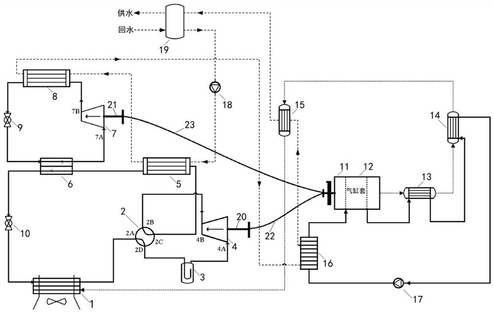
[0035] A high temperature gas heat pump system with mechanical subcooling, including heat pump subsystem, internal combustion engine subsystem, linkage unit and water supply flow path, the structure is as follows figure 1 shown.

[0036] The heat pump subsystem is composed of a heat pump main cycle and a mechanical sub-cooling sub-cycle; The refrigerant channel of the machine 4, the first condenser 5, the high temperature channel of the subcooler 6 and the first throttle valve 10 are sequentially connected in series through pipelines, and the first throttle valve 10 is connected with the low temperature evaporator 1 The refrigerant channels are connected to form a cycle; the subcooler 6 is arranged at the outlet of the first condenser 5 for further condensation and supercooling of the refrigerant; The low-temperature channel of the subcooler 6, the second compressor 7, the second condenser 8, and the second throttle valve 9 are sequentially connected in series through pipelin...

Embodiment 2

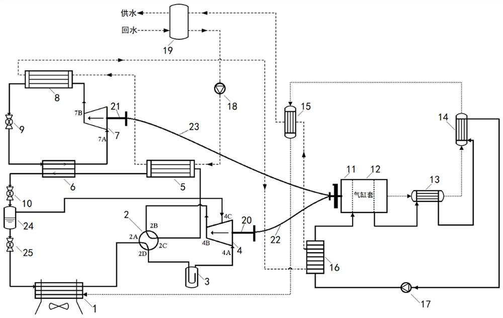
[0060] A high temperature gas heat pump system with mechanical subcooling, including heat pump subsystem, internal combustion engine subsystem, linkage unit and water supply flow path, the structure is as follows image 3 shown.

[0061] Compared with embodiment 1, the first compressor 4 described in embodiment 2 is an air supplementary enthalpy increasing compressor, in addition to having a suction port 4A and an exhaust port 4B, an air supplement port 4C is also added; at this time, the heat pump A flash tank 24 is provided in the main cycle for the separation of liquid refrigerant and gaseous refrigerant after throttling once. The flash tank 24 has a liquid inlet, a liquid outlet and a gas outlet; the first section The flow valve 10 is first connected with the liquid inlet of the flash tank 24, the liquid outlet of the flash tank 24 is connected with the inlet of the third throttle valve 25, and the outlet of the third throttle valve 25 is It is connected with the refriger...

Embodiment 3

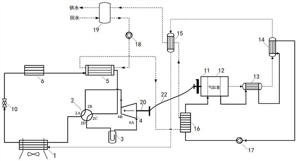
[0065] A high temperature gas heat pump system with mechanical subcooling, including heat pump subsystem, internal combustion engine subsystem, linkage unit and water supply flow path, the structure is as follows Figure 4 shown.

[0066] Compared with Example 1, the heat pump subsystem remains unchanged. Since the engine waste heat belongs to the high-temperature waste heat range, the high-temperature flue gas of the engine can be further used to increase the heating temperature.

[0067] The second flue gas heat exchanger 15 is eliminated in the internal combustion engine subsystem, which is composed of the engine 11, the flue gas flow path and the coolant circulation flow path;

[0068] The flue gas flow path includes the exhaust pipe of the engine 11, the flue gas channel of the three-way catalytic converter 13, the flue gas channel of the first flue gas heat exchanger 14, and the low-temperature evaporation The flue gas channel of device 1;

[0069] The coolant circulat...


PUM


Abstract

The invention discloses a high-temperature gas heat pump system with a mechanical supercooling function. The high-temperature gas heat pump system comprises a heat pump subsystem, an internal combustion engine subsystem, a linkage unit and a water supply flow path. The heat pump main cycle is formed by sequentially connecting a refrigerant channel of a low-temperature evaporator, a four-way reversing valve, a gas-liquid separator, a first compressor, a refrigerant channel of a first condenser, a high-temperature channel of a subcooler and a first throttling valve in series through pipelines. The mechanical subcooling subcycle is formed by sequentially connecting a low-temperature channel comprising the subcooler, a second compressor, a second condenser and a second throttling valve in series through pipelines. The internal combustion engine subsystem is composed of an engine, a flue gas flow path and a cooling liquid circulation flow path. The primary energy utilization rate is high, residual heat of main circulation of the heat pump can be recycled, the higher heat supply temperature is provided, the heat exchange uniformity of the system is obviously improved, irreversible heat exchange loss is reduced, an outdoor evaporator is not prone to frosting, the reliability of an engine is obviously improved, and the service life of the engine is obviously prolonged.

Description

technical field [0001] The invention relates to a gas heat pump system, in particular to a high-temperature gas heat pump system with mechanical supercooling. Background technique [0002] As a clean energy, natural gas plays an important role in my country's energy transformation. my country is steadily promoting the reform of the natural gas system, and the use of high-efficiency energy-saving technologies to improve energy utilization is crucial to the application and development of natural gas. [0003] The gas heat pump has greatly expanded the development space and market demand of gas technology by integrating the two mature technologies of the engine and the vapor compression cycle device. The gas heat pump uses a gas engine to drive the compressor to pump heat from a low-temperature heat source to a high-temperature heat source. It is an efficient and energy-saving device that improves the utilization rate of primary energy. At the same time, the waste heat generat...

Claims


Application Information

Patent Timeline
Patent Type & Authority Applications(China)
IPC IPC(8): F25B30/02F25B30/06F25B41/20F25B43/00F25B47/00F25B47/02
CPCF25B30/02F25B30/06F25B43/00F25B47/006F25B47/02
Inventor 刘猛冯毅徐栎亚唐继旭张刘海张春路何宇佳曹祥
Owner 上海航天工业(集团)有限公司
Learn More