Unlock instant, AI-driven research and patent intelligence for your innovation.

Laser beam splitting system based on double free-form surface reflectors

A technology of curved mirrors and mirrors, which is applied in optics, optical components, instruments, etc., can solve the problems of strong wavelength dependence and deviation of beam splitting effect from the expected design, and achieve the effect of synchronous control and improved degree of freedom

Active Publication Date: 2021-08-31
BEIJING INSTITUTE OF TECHNOLOGYGY
View PDF6 Cites 1 Cited by
  • Summary
  • Abstract
  • Description
  • Claims
  • Application Information

AI Technical Summary

Problems solved by technology

[0009] In view of this, the purpose of the present invention is to solve the strong dependence on the wavelength existing in the existing physical optics beam splitting technology, and the diffraction effect caused by the laser beam in the geometric optics beam splitting technology makes the beam splitting effect deviate from the expected design. The problem is to provide a laser beam splitting system based on double free-form mirrors, which can achieve high-precision beam splitting by synchronously adjusting the illumination and wavefront of the beam, which can be used for off-axis beam splitting

Method used


Image

  • Laser beam splitting system based on double free-form surface reflectors
  • Laser beam splitting system based on double free-form surface reflectors
  • Laser beam splitting system based on double free-form surface reflectors

Examples


Embodiment 1

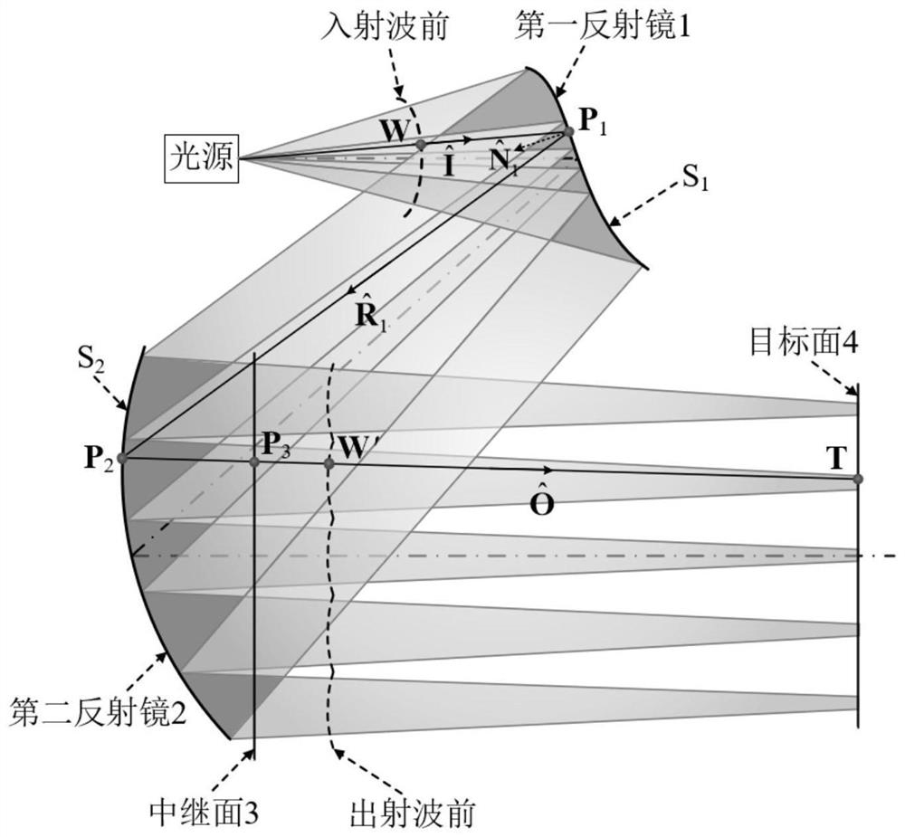
[0060] This embodiment will be partially bundled with the Gaussian point light source before the spherical waves 5 × 5 rectangular uniform camframe array on the target surface, and the spot size and energy in the array are the same. Among them, the light source is located in the system coordinate system, the power is 1 W, the light source wavelength is 532 nm, the divergence angle is θ x_half = 6.235 °, the beam is propagated in the Z axis. First mirror 1 and optical axis 于 于 S1 = 20.7mm, the second mirror 2 is interspersed with the main optical axis (X 2 Y 2 ,z 2 ) = (0, -12, 2.98) mm, relay plane 3 is located in (X 3 Y 3 ,z 3 ) = (0, -12, 8) mm, the relay surface 3 on the Gaussian spot radius is 1.2 mm. The target surface 4 is located after the relay plane 3 4 At 53 mm, the rectangular spot on the target surface was 0.2 mm, and the distance between adjacent two spots was 2.4 mm.

[0061] If the Gaussian energy distribution of the incident beam at the front surface of the first l...

Embodiment 2

[0079] This embodiment will have a Gaussian spherical wave front point light source is a Gaussian beam spot array on the target surface of 5 × 5, the same parameters as in Example 1. Splitting effect on the target surface 4, see Figure 5 .

Embodiment 3

[0081] This embodiment will have a Gaussian point source spherical wave front beam uniform rectangular array of spots on the target surface of 5 × 5, the same array of spot size and energy. Wherein the light source is a wavelength of 632.8 nm, the divergence angle θ x_half = 15.21 °, θ y_half = 9.27 °, beam propagation along the positive z-axis. The first reflecting mirror 1 and the optical axis intersect at z S1 = 16mm, the second reflecting mirror 2 and the main optical axis intersect at (x 2 Y 2 ,z 2 ) = (0, -25, -66.66) mm, the surface 3 is located in the relay (x 3 Y 3 ,z 3 ) = (0, -25, -60) mm, the surface 3 on the relay Gaussian spot radius of 3mm. The target plane is located after the third relay z plane 4 = 23mm, the rectangular beam 4 on the target surface edge length 0.15mm × 0.3mm, the distance between two adjacent spots is 6mm. A first mirror and the second mirror dimensional contour, see FIG. 2 Image 6 . 3 on the surface of the relay preset illuminance distribution, ...


PUM


Abstract

The invention relates to a laser beam splitting system based on double free-form surface reflectors, and belongs to the field of laser beam shaping. The system comprises a first reflecting mirror and a second reflecting mirror, wherein the two reflecting mirrors are both free-form surfaces and can achieve synchronous control over light beam illumination and wavefront, and light beams emitted by a light source form a discrete light spot array on a target surface after passing through the beam splitting system. The incident wavefront W is determined by a light source, the system controls the emergent wavefront W' by defining the illuminance distribution of a relay surface and a target surface, and the illuminance distribution form on the relay surface is a closely arranged Gaussian spot array. The beam splitting system is formed in the mode that light emitted by the light source is split after passing through the reflection system, and finally a light spot array with certain energy distribution is formed on a target face. The reflection beam splitting system is insensitive to the wavelength change of incident light, can effectively weaken the influence of the diffraction effect on the beam splitting result, and is more suitable for the scene of off-axis beam splitting.

Description

Technical field [0001] The present invention relates to a free-form surface based on a dual reflector system, a laser beam, the laser beam shaping art belong. Background technique [0002] The laser beam in a wide parallel laser machining applications such as laser cutting and laser drilling, laser detection and measurement, laser scanning, laser projection, and the structured light illumination optical communication. [0003] The diffractive optical element DOE used by the specified energy into a diffraction order to achieve a beam splitter, a small size and light weight advantages, but its strong dependence on the wavelength, and the high diffraction efficiency and low processing difficulty difficult to balance. Based on optical free-form face of accurate and flexible regulatory capacity of light, people began to seek geometrical optics beam scheme. [0004] Wherein, Jarczynski M, etc. In the article "Jarczynski M, Mitra T, Ivaneko M, etal.Monolithic optical components for spli...

Claims


Application Information

Patent Timeline
Patent Type & Authority Applications(China)
IPC IPC(8): G02B27/14G02B27/10G02B27/00
CPCG02B27/14G02B27/106G02B27/0012
Inventor 冯泽心司佳程德文王涌天
Owner BEIJING INSTITUTE OF TECHNOLOGYGY