A kind of infrared detector and preparation method thereof

An infrared detector and substrate technology, applied in the field of infrared detection, can solve the problems of the increase of the thermal response time of the infrared detector, the increase of the structural thickness of the absorption plate of the infrared detector, and the influence of the infrared detection performance of the infrared detector.

Active Publication Date: 2022-01-18
BEIJING NORTH GAOYE TECH CO LTD
View PDF8 Cites 0 Cited by
  • Summary
  • Abstract
  • Description
  • Claims
  • Application Information

AI Technical Summary

Problems solved by technology

[0003] The infrared detector includes an absorbing plate structure and a beam structure. The performance of the absorbing plate structure and the beam structure directly affects the thermal response performance and detection performance of the infrared detector. Generally, the absorbing plate structure corresponding to the infrared detector needs to make a separate supporting film layer. To support the absorbing plate structure after the infrared detector releases the sacrificial layer, but the setting of the supporting film layer will lead to an increase in the thickness of the infrared detector absorbing plate structure, which will lead to an increase in the thermal response time of the infrared detector and affect the infrared detection of the infrared detector. performance

Method used


Image

  • A kind of infrared detector and preparation method thereof
  • A kind of infrared detector and preparation method thereof
  • A kind of infrared detector and preparation method thereof

Examples


Embodiment Construction

[0047] In order to more clearly understand the above objects, features and advantages of the present disclosure, the solutions of the present disclosure will be further described below. It should be noted that, in the case of no conflict, the embodiments of the present disclosure and the features in the embodiments can be combined with each other.

[0048] In the following description, many specific details are set forth in order to fully understand the present disclosure, but the present disclosure can also be implemented in other ways than described here; obviously, the embodiments in the description are only some of the embodiments of the present disclosure, and Not all examples.

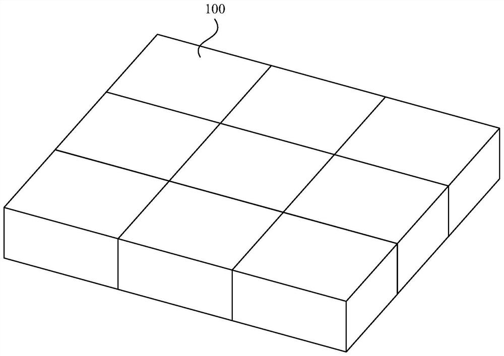
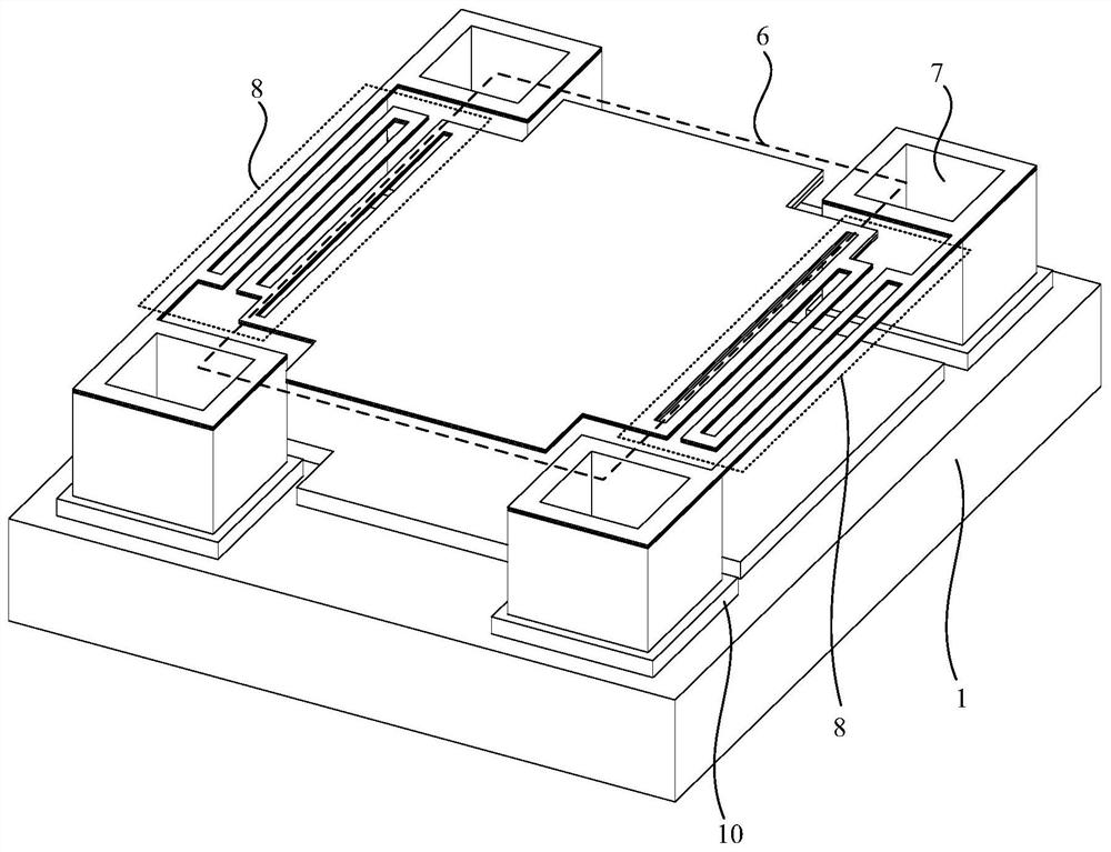
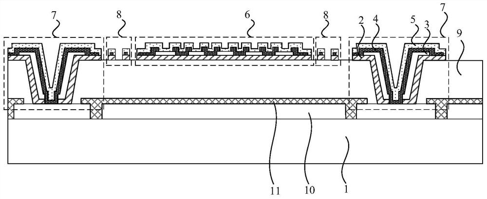
[0049] figure 1 It is a schematic diagram of a three-dimensional structure of an infrared detector provided by an embodiment of the present disclosure, figure 2 A schematic diagram of a three-dimensional structure of an infrared detector pixel provided by an embodiment of the present disclosur...


PUM


Abstract

The present disclosure relates to an infrared detector and a preparation method thereof. The infrared detector includes a substrate, a thermosensitive layer on the substrate, a dielectric layer, an electrode layer and a passivation layer, and the dielectric layer is located between the thermosensitive layer and the electrode layer. , the heat-sensitive layer is located on the side of the dielectric layer close to the substrate, and the passivation layer is located on the side of the electrode layer away from the substrate; the infrared detector includes a plurality of infrared detector pixels arranged in a matrix, and the infrared detector pixel includes an absorbing plate Structure, at least two micro-bridge columns and at least two beam structures, the absorbing plate structure is connected to the corresponding micro-bridge column through the corresponding beam structure; the heat-sensitive layer covers the area where the absorbing plate structure and the beam structure are located, and the passivation layer covers the absorbing plate The region where the structure and the beam structure are located; wherein, the material constituting the heat sensitive layer includes one or more of amorphous silicon, amorphous carbon, amorphous germanium or amorphous silicon germanium. Through the technical proposal of the present disclosure, the thermal response time of the infrared detector is reduced, and the infrared response rate of the infrared detector is improved.

Description

technical field [0001] The present disclosure relates to the technical field of infrared detection, in particular to an infrared detector and a preparation method thereof. Background technique [0002] Non-contact infrared detectors include, for example, non-contact temperature measurement sensors. The detection principle is that the infrared detector converts the infrared radiation signal emitted by the target object to be measured into a heat signal, and converts the heat signal into an electrical signal through the detector sensitive element, and then The electrical signal is processed and output by the circuit chip, and the infrared detector thus realizes the infrared detection function. [0003] The infrared detector includes an absorbing plate structure and a beam structure. The performance of the absorbing plate structure and the beam structure directly affects the thermal response performance and detection performance of the infrared detector. Generally, the absorbin...

Claims


Application Information

Patent Timeline
Patent Type & Authority Patents(China)
IPC IPC(8): H01L31/101H01L31/0216H01L31/18
CPCH01L31/101H01L31/02161H01L31/18Y02P70/50
Inventor 翟光杰潘辉武佩
Owner BEIJING NORTH GAOYE TECH CO LTD
Why Eureka
Try Eureka