Machining method and welding method of steel blank with aluminum-silicon coating

A processing method and welding method technology, applied in welding equipment, laser welding equipment, metal processing equipment, etc., can solve the problems of difficult control and low weld bead strength, achieve stable welding process, improve weld bead shape, and improve toughness and the effect of intensity

Pending Publication Date: 2021-09-03
鞍钢钢材加工配送(长春)有限公司
View PDF14 Cites 0 Cited by
  • Summary
  • Abstract
  • Description
  • Claims
  • Application Information

AI Technical Summary

Problems solved by technology

[0005] The purpose of the present invention is to solve the problems in the prior art that the strength of the weld bead is lower than that of the base metal when the aluminum-silicon-coated steel is directly welded, and the problem that it is difficult to control only the 3 to 10 micron alloy layer after removing the coating is proposed. The processing method and welding method of silicon-coated steel blanks improve production efficiency, the shape of the weld bead is more controllable, and the welding process is more stable

Method used


Image

  • Machining method and welding method of steel blank with aluminum-silicon coating
  • Machining method and welding method of steel blank with aluminum-silicon coating
  • Machining method and welding method of steel blank with aluminum-silicon coating

Examples


no. 1 example

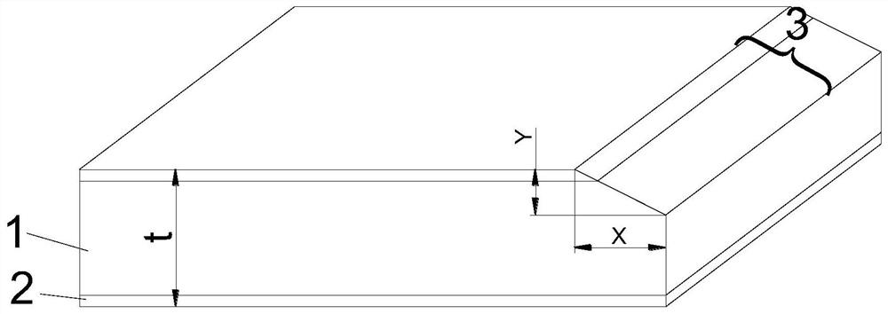
[0050] When the part to be welded is the edge of the blank, the substrate 1 and the pre-coating layer 2 are removed by milling or planing to form a groove structure 3, such as figure 1 As shown, the width X of the groove structure 3 is 0.2-2.3 mm, and the height Y of the groove structure 3 is 0.1 mm-0.7 times the thickness of the blank.

no. 2 example

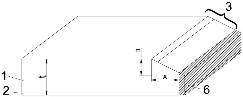
[0052] When the part to be welded is the edge of the blank, the substrate and the pre-coating layer are removed from the part to be welded of the blank to form an initial groove structure, the width of the initial groove structure is 0.3-4mm, and the initial groove structure The height is 0.2mm-0.9 times the thickness of the blank.

[0053] Cutting the initial groove structure according to a plane 6 to obtain a groove structure 3, the width of the groove structure 3 is 0.2mm-2.3mm, and the height of the groove structure 3 is 0.1mm-0.7 times the thickness of the blank.

no. 3 example

[0055] When the part to be welded is the upper middle part of the blank, step S1 specifically includes:

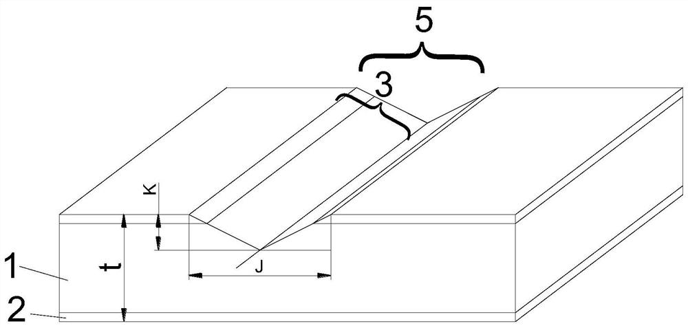
[0056] The removal of the substrate 1 and said pre-coating 2 of the part of the blank to be welded forms a notch structure 5, the person skilled in the art knows how to adapt different specific parameters to the removal operation in order to achieve as complete and rapid removal of part of the substrate as possible And pre-coating, the parameters such as the choice of planing blade type, relative translational speed, pressure. For example, a planer installed on an axis can be used, and the planer is driven to translate in a straight line parallel to the surface of the board to form a notch structure 5 on the surface of the board, such as image 3 shown;

[0057] Cut the blank into two sections from the central axis position of the notch structure 5. Laser shock cutting can be used to cut along a straight line in the middle of the notch, so that the edge of each section of...


PUM

PropertyMeasurementUnit
thicknessaaaaaaaaaa
thicknessaaaaaaaaaa
widthaaaaaaaaaa

Abstract

The invention discloses a machining method and a welding method of a steel blank with an aluminum-silicon coating. The machining method comprises the following specific steps that S1, a base body and a pre-coating of a to-be-welded part of the blank are removed, and at least one groove structure is formed; S2, the roots of the groove structures of at least two blanks make contact to form a welding bead; S3, filling of metal welding wires is conducted for welding; and S4, after welding is completed, cooling is conducted to the normal temperature. According to the machining method and the welding method of the steel blank with the aluminum-silicon coating, the aluminum-silicon coating at the welded position is thoroughly removed in the mode that the edges, to be welded, of plates is beveled, and no surface coating layer is brought into a molten pool in the welding process; and according to the groove structures, the toughness and the strength of a welding joint of aluminum-silicon coating plates can be remarkably improved, and the problems of stamping cracking and delayed cracking of the welding joint due to excessive fusion of aluminum elements in the welding joint during welding of the aluminum-silicon coating plates are solved.

Description

technical field [0001] The invention discloses a processing method of a steel blank with an aluminum-silicon coating and a welding method thereof, belonging to the technical field of blank plate processing and welding. Background technique [0002] As the requirements for automobile exhaust emissions become higher and higher, body weight reduction is one of the most effective ways to reduce automobile exhaust emissions. Hot stamping parts made of hot-formed steel can meet the requirements of body weight reduction and body safety. It has the characteristics of good plasticity, strong forming ability and small springback at high temperature. After hot stamping, the strength can reach more than 1450MPa, which meets the strength and plasticity requirements of automotive structural parts. At present, hot-formed steel includes aluminum-silicon-coated and zinc-coated hot-formed steel, and pre-coating is used to prevent decarburization and surface oxidation of the substrate during h...

Claims


Application Information

Patent Timeline
Patent Type & Authority Applications(China)
IPC IPC(8): B23K26/21B23K26/60
CPCB23K26/21B23K26/60
Inventor 李天姜志公杨保锋
Owner 鞍钢钢材加工配送(长春)有限公司
Why Eureka
Try Eureka