
Optimization design method and system of current transformer electricity-taking power supply

A technology of current transformer and optimized design, applied in the field of optimization design method and system of current transformer power taking power supply, can solve the problems of insufficient power taking power, reducing magnetic permeability of magnetic core, easy saturation of power magnetic core, etc. Convergence speed, avoid output current distortion, improve the effect of defects regardless of hysteresis

Pending Publication Date: 2021-09-03
XI AN JIAOTONG UNIV
View PDF12 Cites 1 Cited by
  • Summary
  • Abstract
  • Description
  • Claims
  • Application Information

AI Technical Summary

Problems solved by technology

[0003] At present, there are two main problems in the power supply of current transformers, that is, when the current of the transmission line is small, the power is insufficient; when the current of the transmission line is large, the power core is easily saturated.
In order to solve the above problems, it is necessary to analyze the transfer characteristics of the current transformer to determine the conditions for the maximum output power of the current transformer, but in most of the analysis and design, the impedance of the power processing module and the load are ignored, so that the impedance of the rear stage is nonlinear. Simple use of resistance as the load, while ignoring the saturation characteristics and hysteresis characteristics of the magnetic core, leads to the results obtained by the analysis, such as the maximum output power point of the current transformer, parameter design, etc., and the actual gap.
On the other hand, the design of the power-taking current transformer generally refers to the design of the current transformer. Although the principles of the two are the same, but the secondary side of the power-taking current transformer needs to output more power when connected to the load, the secondary side of the current transformer It is close to a short circuit, so the design methods of the two are not completely equivalent; in addition, the transmission line has requirements on the volume and weight of the equipment in actual use, but the existing technology does not consider such restrictions while increasing the output power, so that the current mutual inductance It is difficult to select the magnetic core when making the power supply
Finally, the commonly used method of opening an air gap to prevent the saturation of the magnetic core reduces the magnetic permeability of the magnetic core, resulting in a reduction in the output power of the current transformer. Currently, there is a way to control the saturation of the magnetic core by clamping the voltage of the filter capacitor and supplemented by a bleeder circuit. The technology has achieved good results without opening the air gap, and through power analysis, it is determined that the critical capacitor voltage that saturates the magnetic core is the best power point for the current transformer power supply. It is worth noting that the filter capacitor voltage output The DC voltage directly supplies power to modules such as DC / DC, and the critical saturation capacitance voltage of different coils is not equal, so it cannot be set arbitrarily, which leads to defects such as poor versatility in the design of the subsequent power processing module, which increases design difficulty and manufacturing costs.

Method used


Image

  • Optimization design method and system of current transformer electricity-taking power supply
  • Optimization design method and system of current transformer electricity-taking power supply
  • Optimization design method and system of current transformer electricity-taking power supply

Examples


Embodiment Construction

[0072] A method for optimizing the design of a current transformer power supply of the present invention comprises the following steps:

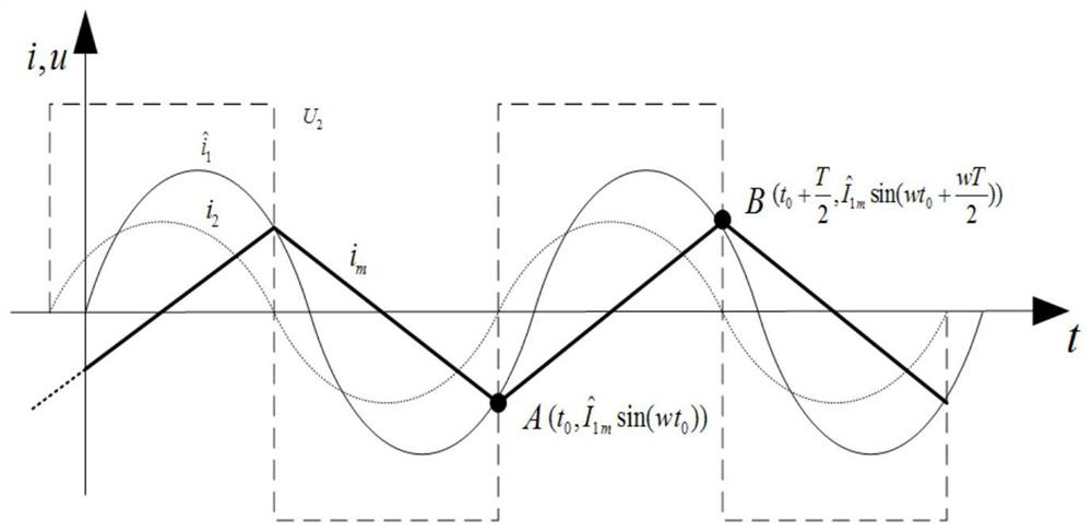
[0073] S1. Establish an output model of the power-taking current transformer that takes into account the influence of the power processing module, analyze the relationship between the output power of the current transformer and the voltage of the filter capacitor, and obtain the maximum output power and the conditions for outputting the maximum power;

[0074] S101. Establish an output model of the power-taking CT taking into account the influence of the power processing module, and obtain a mathematical model that can be used to analyze the output characteristics of the power-taking CT;

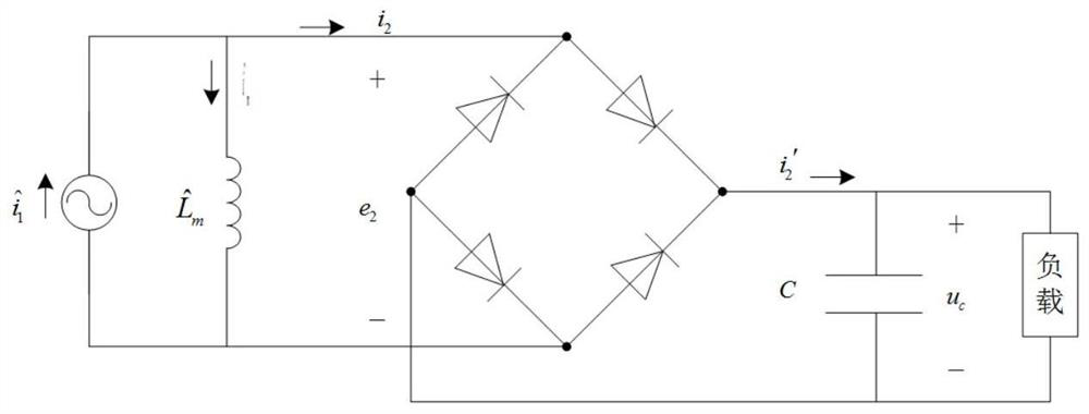
[0075] see figure 1 , in the case of considering the rectifier circuit and the non-linear load of the latter stage, the following assumptions are made for the latter stage of the circuit: Assume that the filter capacitor C is large enough, so when the circ...


PUM


Abstract

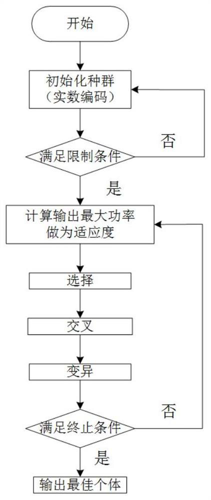
The invention discloses an optimal design method and system of a current transformer electricity-taking power supply, and the method comprises the steps: building an electricity-taking current transformer output model considering the influence of an electric energy processing module, and obtaining the maximum output power and a condition when the maximum power is output; according to the obtained maximum output power, calculating the inner diameter, the outer diameter and the width of the magnetic core when the maximum power is output under the limitation of volume and weight by utilizing a genetic algorithm; selecting a magnetic core by using the obtained magnetic core design parameters, constructing a Jiles-Atherton model hysteresis model, and obtaining magnetic core Jiles-Atherton model parameters through parameter identification; solving an optimal coil turn number N; and according to the obtained maximum output power, the inner diameter, the outer diameter and the width of the magnetic core at the maximum power, the Jiles-Atherton model parameters of the magnetic core and the optimal number of turns of the coil, designing and completing the power supply of the current transformer in cooperation with an electric energy processing module. According to the invention, the power supply can work in an unsaturated region under a specified limited condition and output the maximum power.

Description

technical field [0001] The invention belongs to the technical field of optimized design of a power supply for a current transformer, and in particular relates to an optimal design method and system for a power supply for a current transformer. Background technique [0002] The current transformer (current transformer) power supply developed based on the principle of electromagnetic induction provides continuous and stable power for transmission line monitoring equipment. And the function of converting electrical energy into a stable voltage. Among them, the power-taking current transformer directly obtains electric energy from the transmission line, which plays a decisive role in the output power and saturation characteristics of the power supply. Therefore, it is of great significance to study the design of the power-taking current transformer. [0003] At present, there are two major problems in the power supply of current transformers, that is, when the current of the tr...

Claims


Application Information

Patent Timeline
IPC IPC(8): G06F30/33G06N3/12
CPCG06F30/33G06N3/126
Inventor 唐子健赵彦珍谭驰
Owner XI AN JIAOTONG UNIV
Learn More