
Method for preparing three-dimensional heat dissipation film and three-dimensional heat dissipation film

A heat dissipation film and composite heat dissipation film technology, which is applied in semiconductor/solid-state device manufacturing, semiconductor/solid-state device parts, semiconductor devices, etc., can solve the problems of reduced heat dissipation efficiency and cumbersome placement.

Pending Publication Date: 2021-09-07
STONEPLUS THERMAL MANAGEMENT TECH
View PDF0 Cites 0 Cited by
  • Summary
  • Abstract
  • Description
  • Claims
  • Application Information

AI Technical Summary

Problems solved by technology

[0003] At present, all heat dissipation films are attached to the heat source in a planar manner, that is to say, the heat dissipation film itself has a uniform thickness; however, since the surface of many irregular heating components is not a plane, it cannot be used directly. In the prior art, most heat dissipation films bonded in this planar manner use thermally conductive glue to lay on the surface of these irregular heating elements to form a plane that can be attached to the heat dissipation film, and then use this plane to bond the heat conduction film or Other heat dissipation components; however, the thermal conductivity of general thermal conductivity K<5W / mK, compared with directly pasting the heat dissipation film, resulting in a significant drop in heat dissipation efficiency
[0004] On the other hand, in order to directly use the heat dissipation film, small pieces of heat dissipation film can also be cut out for each relatively small plane on these irregular heating components, and then mounted separately. It will bring repetitive and tedious work to thermal design and subsequent placement

Method used


Image

  • Method for preparing three-dimensional heat dissipation film and three-dimensional heat dissipation film
  • Method for preparing three-dimensional heat dissipation film and three-dimensional heat dissipation film
  • Method for preparing three-dimensional heat dissipation film and three-dimensional heat dissipation film

Examples


Embodiment 1

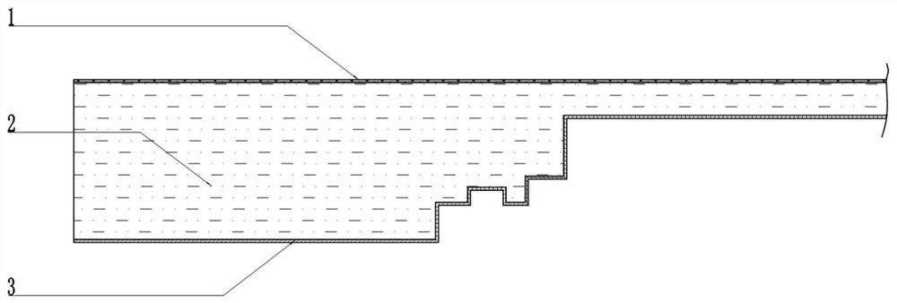
[0040] In this embodiment, a method of layered die-cutting and longitudinal lamination is adopted to form a depression matching the three-dimensional shape of the heat dissipation surface.

[0041] In advance, according to the heat dissipation design requirements, the material and thickness of the three-dimensional heat dissipation film are designed, as well as the specific number of single-layer heat dissipation films and the thickness specifications of each single-layer heat dissipation film, and then the three-dimensional shape of the heat dissipation surface is determined according to the single-layer heat dissipation film and the thickness specification of each single-layer heat dissipation film. The thickness of each single-layer heat dissipation film is divided into corresponding layers, and each single-layer heat dissipation film corresponds to a layer, and then the shape of each layer is obtained;

[0042] Then, according to the designed outline of the three-dimensiona...

Embodiment 2

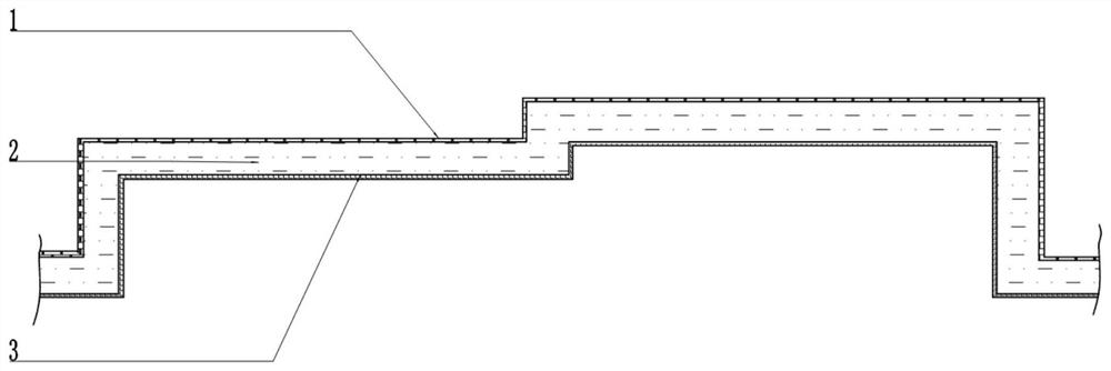
[0048] For some heating components with irregular heat dissipation surfaces, the height difference in the three-dimensional shape of the heat dissipation surface is relatively large, but the heat dissipation design requirements do not require very many (thick) multi-layer composite heat dissipation films, so only use Embodiment 1 The method in the method to shape the depression that matches the three-dimensional shape of the heat dissipation surface will cause waste of material, because the number of layers / thickness of the three-dimensional heat dissipation film in embodiment one depends on the height of the highest point in the three-dimensional shape; in addition, if the heating element The installation space of the device itself is limited. For example, there is an intermittent fit between the installation space and the heat dissipation surface of the heating element, so the space left for the multilayer composite heat dissipation film is extremely limited.

[0049] However...

Embodiment 3

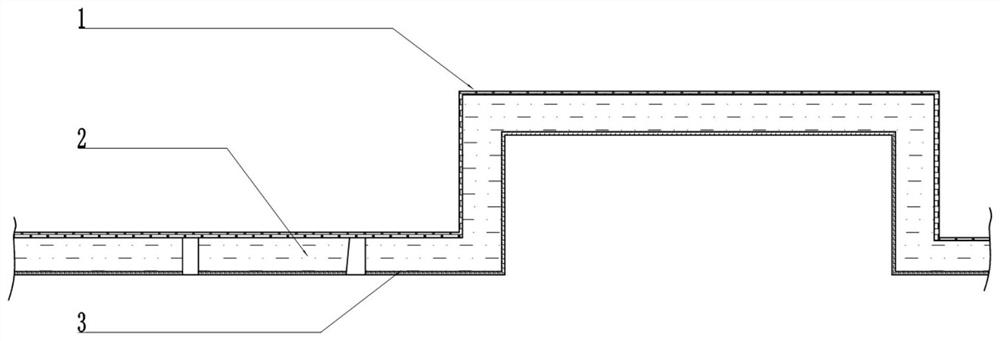
[0058] In this embodiment, layered die-cutting and longitudinal lamination are used to form a depression matching the three-dimensional shape of the heat dissipation surface, and then molding is used to form the remaining depressions.

[0059] In advance, according to the heat dissipation design requirements, the material and thickness of the three-dimensional heat dissipation film are designed, as well as the specific number of single-layer heat dissipation films and the thickness specifications of each single-layer heat dissipation film, and then the lower part of the three-dimensional shape of the heat dissipation surface (required The shallower depression and its dominance) are divided into corresponding layers according to the thickness of the single-layer heat dissipation film and each single-layer heat dissipation film, and each single-layer heat dissipation film corresponds to a layer, and then the shape of each layer is obtained; The three-dimensional shape of the rest...


PUM

PropertyMeasurementUnit
thicknessaaaaaaaaaa
thicknessaaaaaaaaaa
thicknessaaaaaaaaaa

Abstract

The invention relates to the technical field of heat dissipation films, and particularly discloses a method for preparing a three-dimensional heat dissipation film and the three-dimensional heat dissipation film prepared based on the method. The method comprises the steps of 1, obtaining the three-dimensional shape of a surface needing heat dissipation; and 2) forming a recess matched with the three-dimensional shape on the single-layer or multi-layer composite heat dissipation film to obtain the three-dimensional heat dissipation film. The method is simple in process and easy to operate, and the heat dissipation film in the three-dimensional shape is directly prepared through die cutting or die forming, so that the heat dissipation requirement of heating electronic devices in irregular shapes is met, and the defect that traditional heat conduction glue is low in heat dissipation efficiency is overcome.

Description

technical field [0001] The invention relates to the technical field of heat dissipation films, and specifically discloses a method for preparing a three-dimensional heat dissipation film and the three-dimensional heat dissipation film. Background technique [0002] Smartphones, laptops, smart AR, VR wearables, smart homes, and display screens are developing rapidly. In order to meet functional specialization, diversification, and portability, the integration of chips and the compactness of each component are getting higher and higher. Ultimately, The result is increased power consumption and smaller heat dissipation space, causing many similar smart products to easily heat up. At present, the most widely used heat dissipation film (usually thermal conductivity K≥1200W / mK) is synthetic graphite heat dissipation film, and graphene heat dissipation film (also known as graphene heat conduction film) is used in individual mobile phone terminals. [0003] At present, all heat dis...

Claims


Application Information

Patent Timeline
Patent Type & Authority Applications(China)
IPC IPC(8): H01L21/48H01L23/367
CPCH01L21/4871H01L23/3672
Inventor 吴召洪周中期
Owner STONEPLUS THERMAL MANAGEMENT TECH
Learn More