Environment-friendly dust removal winding device for metallurgical metal wires

A metal wire, winding device technology, applied in the direction of metal extrusion, metal processing equipment, metal extrusion cleaning equipment, etc., can solve the problem of easy mess, can not clean and collect the dust on the surface of the metal wire, etc.

Active Publication Date: 2021-09-10
唐山瑞泰合金制造有限公司
View PDF5 Cites 0 Cited by
  • Summary
  • Abstract
  • Description
  • Claims
  • Application Information

AI Technical Summary

Problems solved by technology

At present, the existing winding device is easy to be messy during winding, which cannot meet the needs of actual use, and cannot clean and collect the dust on the surface of the metal wire. Therefore, we propose an environmentally friendly dust collector for metallurgical metal wire. volume device

Method used


Image

  • Environment-friendly dust removal winding device for metallurgical metal wires
  • Environment-friendly dust removal winding device for metallurgical metal wires
  • Environment-friendly dust removal winding device for metallurgical metal wires

Examples


Embodiment 1

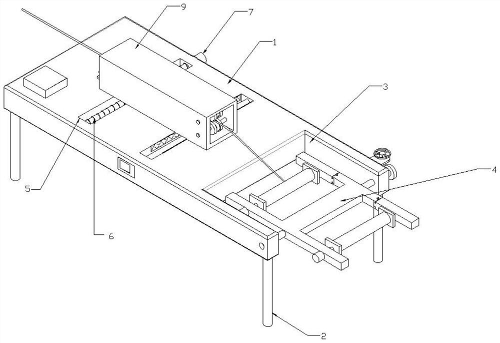
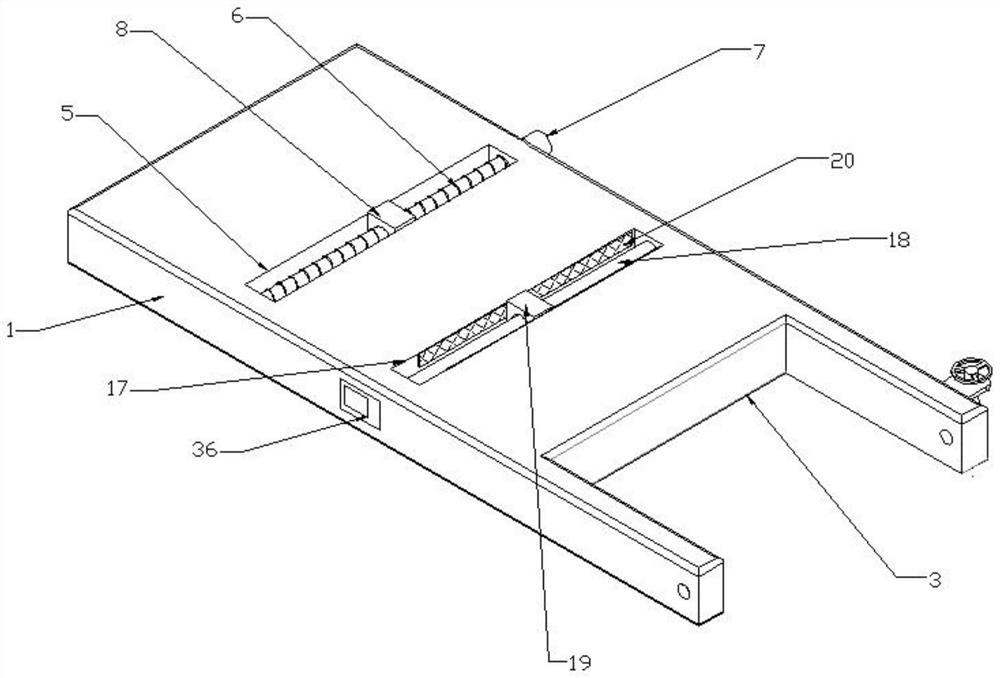
[0028] see Figure 1-2 As shown, the present embodiment is an environment-friendly dedusting and rewinding device for metallurgical metal wire rods, including a workbench 1, the four corners of the bottom of the workbench 1 are connected with uprights 2, and the right end of the workbench 1 is provided with an assembly port 3, and inside the assembly port 3 A coil rack 4 is provided, a longitudinal groove 5 is provided on the top of the workbench 1, and a screw rod 6 is connected to the longitudinal groove 5 for rotation, and a drive motor 7 is connected to the rear end of the screw rod 6, and the drive motor 7 is fixedly connected to the outer wall of the workbench 1 , the outer wall of the screw mandrel 6 is screwed with a nut seat 8, and the upper end of the nut seat 8 protruding from the longitudinal groove 5 is connected with a wire box 9.

[0029] The concrete implementation manner of this embodiment is:

[0030] When the device is in use, it is connected to an external...

Embodiment 2

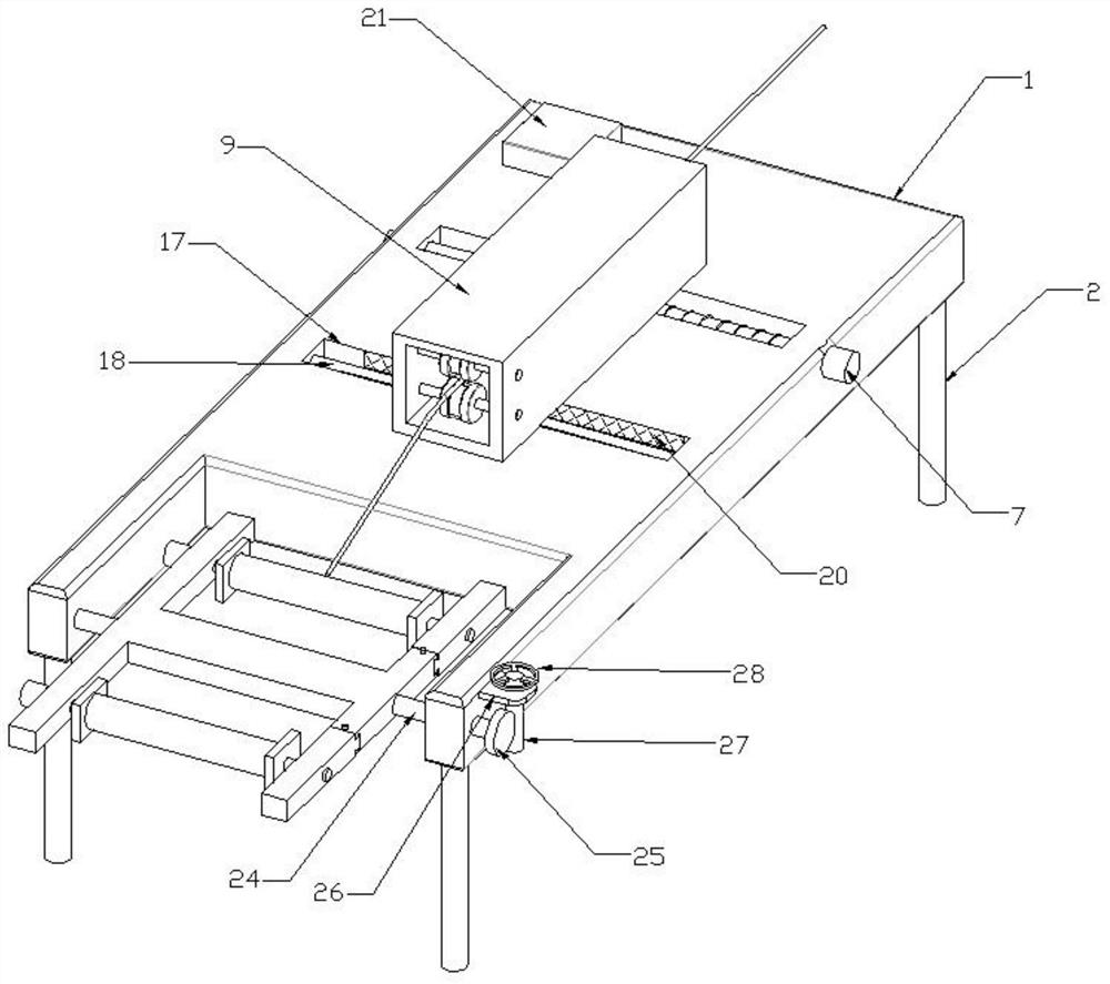
[0032] see Figure 1-4 As shown, on the basis of Embodiment 1, the left and right ends of the wire passing box 9 are opened, the front and rear sides of the inner cavity of the wire passing box 9 are connected with cleaning motors 10, and the power output end of the cleaning motor 10 is connected with a cleaning brush 11 , the positions of the two cleaning motors 10 are staggered, and the bottom of the inner cavity of the wire passing box 9 is provided with a slot 12, and an electrostatic precipitator 13 is movably inserted in the slot 12, and the left end of the electrostatic precipitator 13 is connected with a handle 14, and the wire passing The inner cavity right part of box 9 is symmetrically connected with mounting frame 15 up and down, and the end portion of mounting frame 15 is equipped with guide wheel 16, and the outer wall of two guide wheels 16 all offers annular groove.

[0033] The top of the workbench 1 is provided with a limit groove 17, the limit groove 17 is a...


PUM


Abstract

The invention discloses an environment-friendly dust removal winding device for metallurgical metal wires, which comprises a workbench, wherein stand columns are connected to the four corners of the bottom of the workbench, an assembling opening is formed in the right end of the workbench, a material winding frame is arranged in the assembling opening, a longitudinal groove is formed in the top of the workbench, a lead screw is rotationally connected into the longitudinal groove; the rear end of the lead screw is connected with a driving motor, the driving motor is fixedly connected with the outer wall of the workbench, the outer wall of the lead screw is in threaded connection with a nut seat, and the upper end, extending out of the longitudinal groove, of the nut seat is connected with a wire passing box. The environment-friendly dust removal winding device is reasonable in structural design, avoids the problem that one end of a winding frame is stacked, protects the cleanliness of the working environment, achieves the good environment-friendly effect, can conveniently collect and treat dust and impurities after power failure, and guarantees the work efficiency of metal wire winding.

Description

technical field [0001] The invention relates to the technical field of equipment related to metallurgical metal wires, in particular to an environment-friendly dedusting and winding device for metallurgical metal wires. Background technique [0002] Metallurgy refers to the process and technology of extracting metals or metal compounds from minerals, and using various processing methods to make metals into metal materials with certain properties. Metallurgy has a long history of development, from the Stone Age to the subsequent Bronze Age, to the large-scale development of modern iron and steel smelting. The history of human development incorporates the history of metallurgy. Metallurgical technologies mainly include pyrometallurgy, hydrometallurgy and electrometallurgy. With the successful application of physical chemistry in metallurgy, metallurgy has moved from technology to science, so there is a metallurgical engineering major in universities. [0003] Metal wire rod...

Claims


Application Information

Patent Timeline
Patent Type & Authority Applications(China)
IPC IPC(8): B21C47/12B21C43/00B21C47/24B08B1/02B08B6/00
CPCB21C47/12B21C43/00B21C47/245B08B1/02B08B1/002B08B6/00
Inventor 何首腰
Owner 唐山瑞泰合金制造有限公司
Why Eureka
Try Eureka