Process chamber with water vapor evaporation system

A technology of water vapor evaporation and process chamber, which is applied in the direction of electrical components, semiconductor/solid-state device manufacturing, circuits, etc., and can solve problems such as wasting production capacity, damaging the process tube chamber, and increasing the workload of staff

Pending Publication Date: 2021-09-10
赛瑞达智能电子装备(无锡)有限公司
View PDF0 Cites 0 Cited by
  • Summary
  • Abstract
  • Description
  • Claims
  • Application Information

AI Technical Summary

Problems solved by technology

[0002] Conventional usage, is BBr 3 After the process of the low-pressure diffusion furnace, boric acid and other substances will gradually remain on the inner wall of the process chamber, the position of the furnace mouth and the furnace door, which is sticky. , the furnace door cannot be opened normally, the inner wall of the process tube also has viscous substances remaining, and the boats inside the process chamber are adhered. In this case, it is necessary to stop working, turn off the power of the heater and cool down, and wait for the working temperature of 1050 ° C to drop to When it is close to room temperature, disassemble, clean or replace the process tube chamber set inside the heater. A disassembly or replacement requires at least two shifts, of which the cooling time takes 12-15 hours, and the replacement takes 2-3 hours , waste production capacity, increase the workload of the staff, and may damage the process tube chamber (quartz material) during disassembly, cleaning, and replacement

Method used


Image

  • Process chamber with water vapor evaporation system
  • Process chamber with water vapor evaporation system
  • Process chamber with water vapor evaporation system

Examples


Embodiment Construction

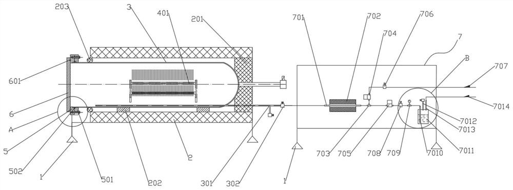
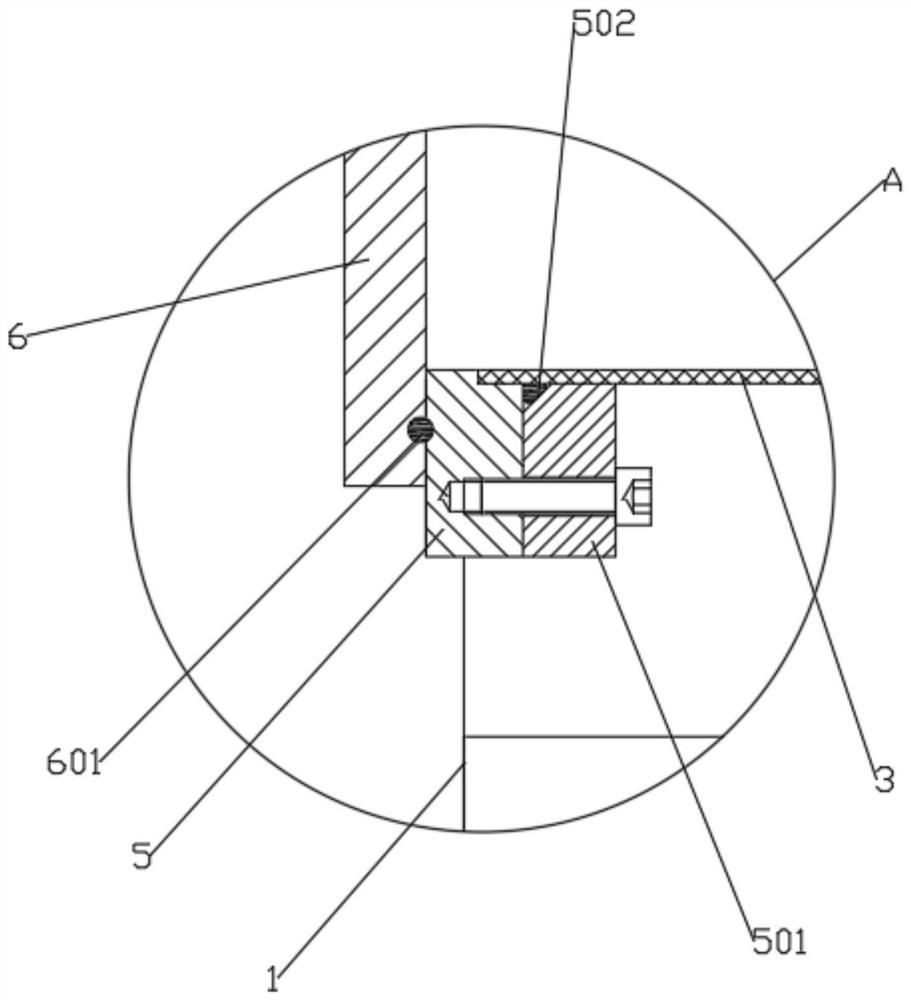
[0019] The present invention is specifically described below in conjunction with accompanying drawing, as Figure 1-4 As shown, by the frame body 1, the heater 2 supported by the frame body 1, the inside of the heater 2 is coaxially installed with the process tube 3 (process furnace) through the pad 202, and the crystal boat 401 and the wafer 402 are placed on the process tube 3 (process furnace). Furnace), the process furnace mouth flange 5 supported by the frame, the process tube 3 sealing flange, and the process tube 3 sealing ring are used to seal and install the process tube 3 (process furnace) nozzle, and the swing furnace door 6 passes through the furnace The door sealing ring and the process furnace mouth flange 5 realize the furnace door sealing, the tail heat insulation plug is used to block the heat dissipation at the tail of the heater 2, and the mouth insulation soft block 203 is used to block the heater 2 and the process tube 3 (process furnace) The gap between t...


PUM


Abstract

The invention discloses a process chamber with a water vapor evaporation system, which comprises a frame body. Heaters are mounted on the frame body, process pipes are mounted on the inner sides of the heaters, the process pipes are mounted between the heaters and are fixedly mounted in a non-contact manner, and a process pipe sealing flange is arranged at a pipe orifice of each process pipe to press a process pipe sealing ring. A swing furnace door is arranged on the outer side of the pipe orifice, a process gas inlet pipe is arranged on the inner wall of the lower end of the process pipe, one end of the process gas inlet pipe is connected with a gas inlet valve, and the other end of the gas inlet valve is connected with a water vapor evaporation system through a connecting pipe. The process chamber with a water vapor evaporation system has the beneficial effects thatwater vapor is introduced after the normal boron diffusion process, water vapor entering the process chamber performs water vapor neutralization on residual chemical substances in the original process chamber, so that the phenomena that residual substances are generated in the process chamber and a pipe orifice, the process chamber is adhered to a furnace door and the interior of the process chamber is not clean are avoided, the disassembly and cleaning period of the process chamber is prolonged, the equipment utilization rate is improved, the productivity is improved, and the process pipe disassembly and replacement workload is reduced.

Description

technical field [0001] The invention relates to the technical field of tubular low-pressure boron diffusion furnaces and oxidation furnaces in the field of photovoltaics and semiconductors, in particular to a process chamber with a water vapor evaporation system. Background technique [0002] Conventional usage, is BBr 3 After the process of the low-pressure diffusion furnace, boric acid and other substances will gradually remain on the inner wall of the process chamber, the position of the furnace mouth and the furnace door, which is sticky. , the furnace door cannot be opened normally, and the inner wall of the process tube also has viscous substances remaining. For the adhesion of the boat inside the process chamber, in this case, it is necessary to stop working, turn off the power of the heater and cool down, and wait for the working temperature of 1050 ° C to drop to When it is close to room temperature, disassemble, clean or replace the process tube chamber set inside...

Claims


Application Information

Patent Timeline
IPC IPC(8): H01L21/67
CPCH01L21/67017
Inventor 宋立禄张海林滕玉朋刘国霞吴寄浩
Owner 赛瑞达智能电子装备(无锡)有限公司
Why Eureka
Try Eureka