Microstrip low-pass filter, transmission zero point determination method and transmission zero point frequency setting method
A low-pass filter and transmission zero technology, applied in the field of communication systems, can solve the problems of unfavorable system miniaturization and large circuit size, etc.
- Summary
- Abstract
- Description
- Claims
- Application Information
AI Technical Summary
Problems solved by technology
Method used
Image

Examples
Embodiment 1
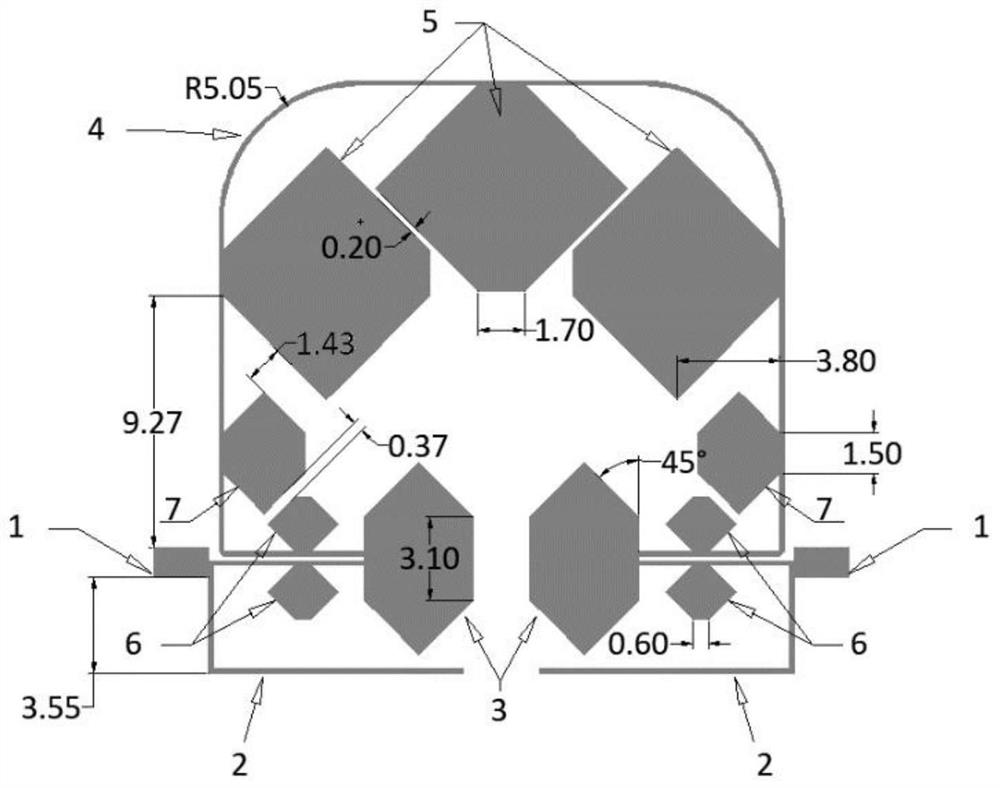
[0038] Embodiment 1 of the present invention provides a microstrip low-pass filter, such as figure 1 As shown, it includes input and output ports 1, a pair of high-impedance open-circuit stubs 2, a pair of parallel coupled lines loaded with hexagonal resonators 3, folded high-impedance transmission lines 4, three-stage cascaded hexagonal coupled resonators 5, two Back-to-back hexagonal resonators 6, a pair of single-stage hexagonal resonators 7. The filter circuit is manufactured by Rogers4003 substrate, and the thickness of the substrate is 0.508mm. Wherein, the input and output port 1 is a straight microstrip transmission line, and the characteristic impedance of the transmission line is 50 ohms. The input and output port 1 is used to weld a 50-ohm connector to realize the assembly and integration of the circuit. The input and output ports 1 are directly connected to a pair of high-impedance open stubs 2 and a pair of parallel coupled lines 3 loaded with hexagonal resonato...
Embodiment 2
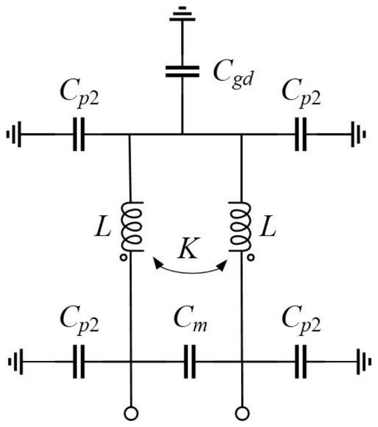
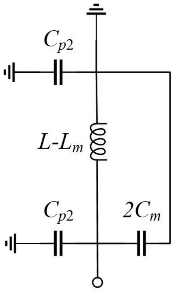
[0042]Embodiment 2 of the present invention provides a method for determining the number of transmission zeros. It should be noted that the present invention aims at realizing an ultra-wide stopband while ensuring sufficient stopband suppression. The more transmission zeros in the stop band of the filter, the higher the stop band suppression degree; the larger the frequency span of each transmission zero point setting, the larger the stop band range, and an ultra-wide stop band can be formed. Determining the number and frequency of zero points here can clarify the stop band action range of each resonator, and accurately optimize the stop band characteristics. The parallel coupled line 3 loaded with a hexagonal resonator is composed of a high-impedance parallel coupled line and a hexagonal resonator. Its LC equivalent circuit, odd-mode equivalent circuit, and even-mode equivalent circuit are respectively shown as figure 2 , image 3 , Figure 4 shown. The number of zeros ge...
Embodiment 3
[0063] Embodiment 3 of the present invention provides a method for setting the frequency of transmission zeros. The method for determining the number of transmission zeros in Embodiment 2 above is used to determine the number of transmission zeros of parallel coupled lines loaded with hexagonal resonators. The effective capacitance and inductance value can set the transmission zero frequency, which helps to accurately optimize the design of ultra-wide stopband.
PUM
 Abstract
Description
Claims
Application Information
 - R&D
- Intellectual Property
- Life Sciences
- Materials
- Tech Scout
- Unparalleled Data Quality
- Higher Quality Content
- 60% Fewer Hallucinations
Browse by: Latest US Patents, China's latest patents, Technical Efficacy Thesaurus, Application Domain, Technology Topic, Popular Technical Reports.
© 2025 PatSnap. All rights reserved.Legal|Privacy policy|Modern Slavery Act Transparency Statement|Sitemap|About US| Contact US: help@patsnap.com