
Ventilation pipeline capable of preventing particles from entering interior to precipitate and accumulate

A technology for ventilation ducts and air inlet ducts, which is applied in the directions of duct layout, space heating and ventilation, space heating and ventilation details, etc., and can solve problems such as air secondary pollution, reduce air quality in buildings, and reduce duct circulation.

Inactive Publication Date: 2021-09-14
丽水大广通环保科技工程有限公司
View PDF6 Cites 1 Cited by
  • Summary
  • Abstract
  • Description
  • Claims
  • Application Information

AI Technical Summary

Problems solved by technology

[0003] The purpose of the present invention is to provide a ventilation duct that prevents particles from entering the interior and depositing. It has the advantages of anti-clogging, easy maintenance, and good stability. It will deposit and accumulate on the inner wall of the pipeline, which will not only cause secondary pollution to the air when the air flows and reduce the air quality in the building, but also easily deposit and accumulate at the bend, causing blockage and reducing the circulation of the pipeline.

Method used

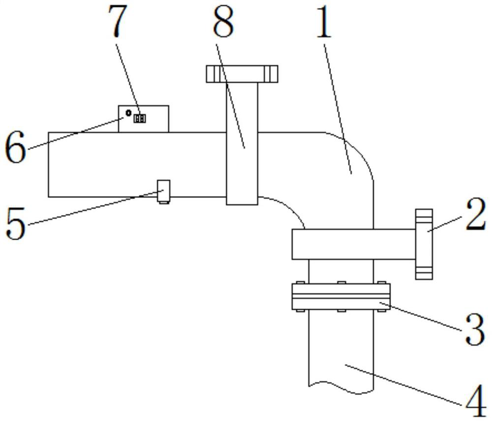
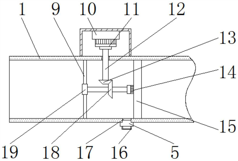
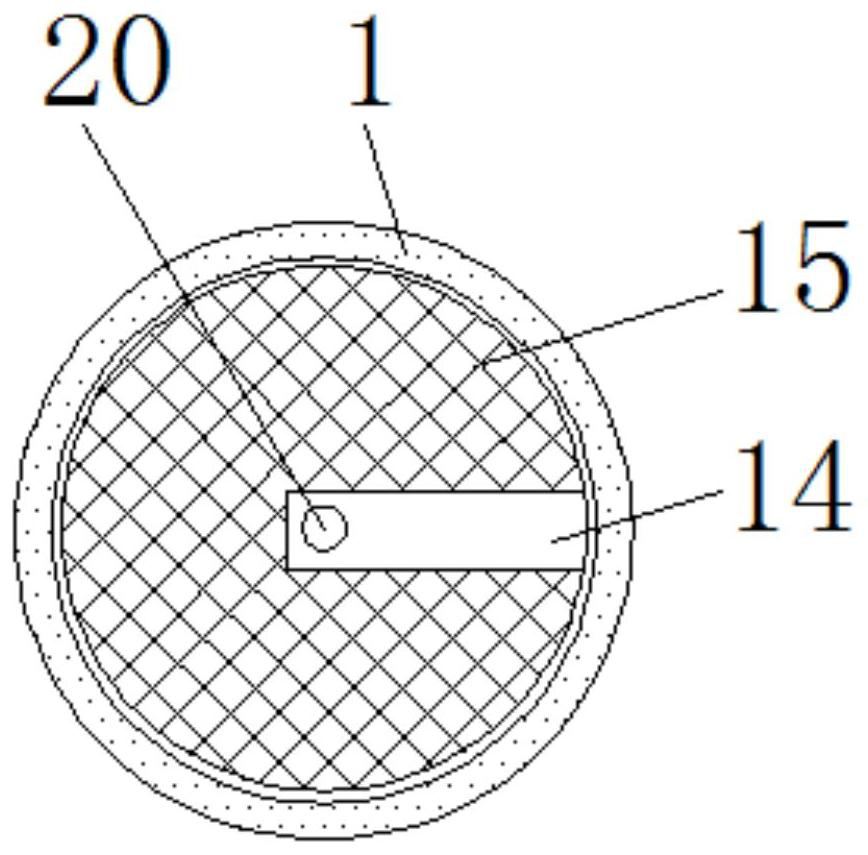

Image

  • Ventilation pipeline capable of preventing particles from entering interior to precipitate and accumulate
  • Ventilation pipeline capable of preventing particles from entering interior to precipitate and accumulate
  • Ventilation pipeline capable of preventing particles from entering interior to precipitate and accumulate

Examples


Embodiment Construction

[0017] The following will clearly and completely describe the technical solutions in the embodiments of the present invention with reference to the accompanying drawings in the embodiments of the present invention. Obviously, the described embodiments are only some, not all, embodiments of the present invention. Based on the embodiments of the present invention, all other embodiments obtained by persons of ordinary skill in the art without making creative efforts belong to the protection scope of the present invention.

[0018] In the description of the invention, it should be noted that the terms "upper", "lower", "inner", "outer", "front end", "rear end", "both ends", "one end", "another end" etc. The indicated orientation or positional relationship is based on the orientation or positional relationship shown in the drawings, and is only for the convenience of describing the present invention and simplifying the description, rather than indicating or implying that the referre...


PUM


Abstract

The invention discloses a ventilation pipeline capable of preventing particles from entering the interior to precipitate and accumulate. The ventilation pipeline comprises an air inlet pipe, a flange is arranged at the lower end of the air inlet pipe, a connecting pipe is arranged at the lower end of the flange, a machine box is fixedly connected to the upper end of the left side of the air inlet pipe, a rotating motor is arranged at the upper end of an inner cavity of the machine box, the output end of the rotating motor is fixedly connected with a power rod, the lower end of the power rod penetrates through the air inlet pipe and is provided with a driving gear in a sleeved mode, and a transmission rod is arranged below the driving gear. According to the ventilation pipeline, through the arrangement of a filter screen, filtering can be carried out on circulating air, so that the phenomenon that dust enters a bent part to cause accumulation and blockage is avoided; and through the arrangement of the machine box, the rotating motor, the power rod, the driving gear, a cleaning brush, a dust discharging opening, a driven gear and the transmission rod, and cleaning can be automatically carried out on the surface of the filter screen, so that dust is prevented from being gathered on the surface of the filter screen to influence air circulation, and cleanness and circulation of the interior of the air inlet pipe are effectively kept.

Description

technical field [0001] The invention relates to the technical field of ventilation ducts, in particular to a ventilation duct that prevents particles from entering and accumulating inside. Background technique [0002] Ventilation duct is the abbreviation of ventilation duct. It is a metal or non-metallic pipe used in ventilation and air-conditioning engineering of industrial and civil buildings. Ventilation duct is a municipal infrastructure for air circulation and reduction of harmful gas concentration. The top is set on the top of the building, and because of the strong wind on the top of the building, a large amount of air will be poured into the interior from the opening at the top and delivered to the building, and the air that is poured in will contain a large amount of air. Dust particles, and some of these dust particles will deposit and accumulate on the inner wall of the pipe, which will not only cause secondary pollution to the air when the air flows and reduce t...

Claims


Application Information

Patent Timeline
IPC IPC(8): F24F13/02F24F13/28F24F13/32F24F8/108F24F8/90F24F11/52F24F11/89
CPCF24F13/0245F24F13/28F24F13/32F24F11/52F24F11/89F24F8/108F24F8/90
Inventor 刘广东
Owner 丽水大广通环保科技工程有限公司
Learn More