
A plasma mass spectrometry ion focusing deflection sampling interface and working mode

A sampling interface and ion focusing technology, applied in electron/ion optical devices, particle separation tubes, sample introduction/extraction, etc., can solve problems such as low transmission efficiency, affecting sample ionization efficiency, and large ion loss, achieving high Effects of ion transmission efficiency, increased injection throughput, and back-end detection sensitivity

Active Publication Date: 2022-05-20
INSTITUTE OF ANALYSIS GUANGDONG ACADEMY OF SCIENCES (CHINA NATIONAL ANALYTICAL CENTER GUANGZHOU)
View PDF8 Cites 0 Cited by
  • Summary
  • Abstract
  • Description
  • Claims
  • Application Information

AI Technical Summary

Problems solved by technology

Commonly used ion transmission interfaces include photon baffle type, off-axis deflection type, and 90-degree deflection type, etc. The photon baffle type has the problems of large ion loss, low transmission efficiency and mass discrimination; in the off-axis deflection type transmission interface, the sample substrate directly It is difficult to clean and maintain the lens parts on the surface of the ion lens, and the photon baffle type and off-axis deflection type mostly use horizontally placed rectangular tubes. Due to the thermal diffusion effect of the rectangular tube and plasma, there is a temperature difference between the upper and lower ends, which affects the temperature of the sample. ionization efficiency
Vertically placing the rectangular tube can solve the problem of the temperature difference of the rectangular tube. The existing vertically placed instruments mostly use deflection electrodes plus ion lenses or ion funnels during ion introduction. Although this method improves the selectivity of ions, but due to The flight path is longer, and the number of target ions entering the mass spectrometer will be reduced, resulting in a decrease in detection sensitivity
In addition, the combination of the two methods increases the volume of key components, which is extremely sensitive to trace moisture in the aerosol, and cannot fully atomize the sample metal elements.
When the sample enters the mass spectrometer through the plasma flame, it mostly exists in the form of metal ion conjugates composed of sample elements and different anions or water molecules, which are reflected in the mass spectrum as multiple mass spectrum peaks with different mass numbers, causing interference to mass spectrometry detection , which also reduces the sensitivity of the sample

Method used


Image

  • A plasma mass spectrometry ion focusing deflection sampling interface and working mode
  • A plasma mass spectrometry ion focusing deflection sampling interface and working mode

Examples


Embodiment

[0025] It should be noted that the terms "first" and "second" in the description and claims of the present invention and the above drawings are used to distinguish similar objects, but not necessarily used to describe a specific sequence or sequence. It is to be understood that the data so used are interchangeable under appropriate circumstances such that the embodiments of the invention described herein can be practiced in sequences other than those illustrated or described herein. In addition, the terms "comprising" and "having" and any variations thereof in the embodiments of the present invention are intended to cover a non-exclusive inclusion, for example, a process, method, system, product or device comprising a series of steps or units is not necessarily limited to Those steps or elements are not explicitly listed, but may include other steps or elements not explicitly listed or inherent to the process, method, product or apparatus.

[0026] It is to be understood that ...

Embodiment approach 1

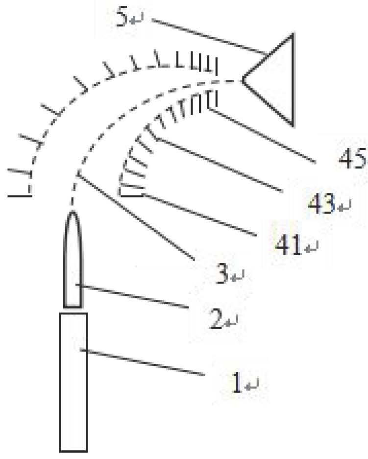
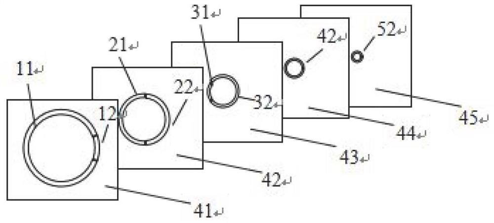
[0035] In the positive ion deflection working mode, a plasma mass spectrometry ion focusing deflection sample injection interface consists of a plasma source composed of a plasma torch 1 and a plasma flame 2, a focusing deflection plate group composed of several deflection plates, and a mass spectrometry sample injection interface. Interface composition. The plasma source is high-power microwave plasma or inductively coupled plasma. Taking partial focusing deflecting plates 41-45 arranged sequentially in the focusing deflecting plate group as an example, focusing deflecting plates 41-45 are a series of deflecting plates with a circular central channel, and each deflecting plate is distributed at a certain angle in the plasma flame 2 Between it and the mass spectrometry sampling interface 5, its central channel forms the ion transmission path 3 for ions to enter the mass spectrometry sampling interface from the source. The dimensions of the central channels of the focusing def...

Embodiment approach 2

[0038] In the negative ion deflection working mode, a plasma mass spectrometer ion focusing deflection sampling interface consists of a plasma source composed of a plasma torch 1 and a plasma flame 2, a focusing deflection plate group composed of several deflection plates, and a mass spectrometry sampling interface composition. The plasma source is a low-power microwave plasma, and the structure of the focusing deflection plasma mass spectrometry sampling interface is the same as that in Embodiment 1. Taking the focus deflection plates 41-45 arranged sequentially in the focus deflection plate group as an example, the electrodes 11, 21 and 31 on them are loaded with a voltage of U 11 , U 21 and U 31 , the loading voltage on the electrodes 12~52 is U 12 ~ U 52 , its voltage value increases from the ion source terminal to the mass spectrometer injection interface terminal, that is, U 11 21 31 ,U 12 22 32 42 52 . There is a potential difference between the electrode pairs o...


PUM


Abstract

The invention discloses a plasma mass spectrometer ion focus deflection sampling interface and working mode, which relates to an ion optical device, which includes: a plasma source, which forms plasma through gas ionization; several focus deflection plates, Each of the focusing deflection plates has a circular central channel, and deflection electrode pairs are distributed on the edge of the circular central channel. between interfaces. The invention simultaneously realizes effective separation of photons and neutral particles and ion focusing during the ion transmission process.

Description

technical field [0001] The invention relates to an ion optical device, in particular to a plasma mass spectrometer ion focusing deflection sampling interface and a working mode. Background technique [0002] The sampling interface of the plasma mass spectrometer refers to the device that connects the plasma source and the mass spectrometer detector, and controls the target ion that is excited and ionized from the matrix to enter the mass spectrometer detector inlet. The ion sampling interface is in the middle hub between the plasma source that excites the sample and the mass analyzer. Its importance is to efficiently transmit the sample ions generated by the plasma source to the mass analyzer, which is important for the ion detection sensitivity and detection limit performance. influences. During the excitation process of the sample by the plasma source, with the generation of ions, a large number of photons and neutral particles will be generated at the same time. One of t...

Claims


Application Information

Patent Timeline
Patent Type & Authority Patents(China)
IPC IPC(8): H01J49/06H01J49/04
CPCH01J49/06H01J49/061H01J49/0422
Inventor 雷永乾郭鹏然陈江韩梁维新
Owner INSTITUTE OF ANALYSIS GUANGDONG ACADEMY OF SCIENCES (CHINA NATIONAL ANALYTICAL CENTER GUANGZHOU)
Learn More