
Maximum power point tracking method under local shadow condition

A technology of maximum power point and partial shadow, applied in the direction of instruments, control/regulating systems, regulating electrical variables, etc., can solve the problems of complex parameter setting, poor tracking accuracy, low power generation efficiency, etc., to achieve strong search ability and improve tracking speed. and precision, easy to achieve results

Active Publication Date: 2021-09-21
SHANGHAI DIANJI UNIV
View PDF9 Cites 2 Cited by
  • Summary
  • Abstract
  • Description
  • Claims
  • Application Information

AI Technical Summary

Problems solved by technology

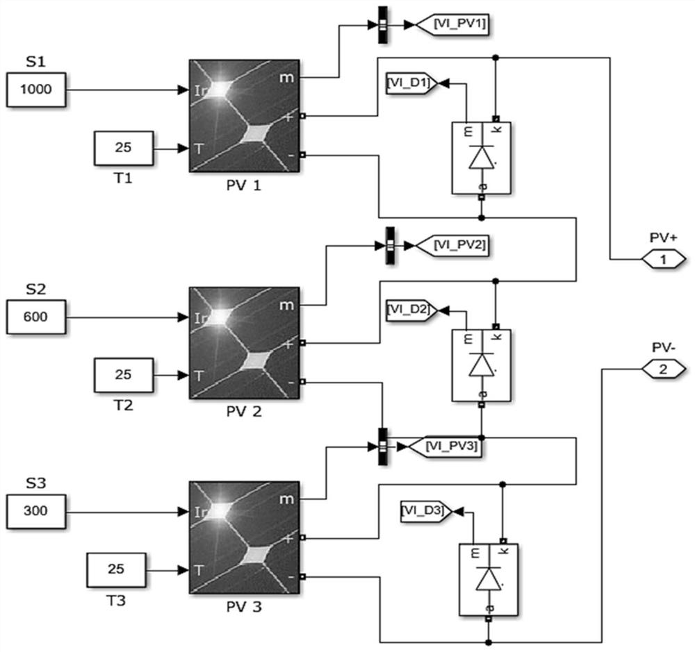
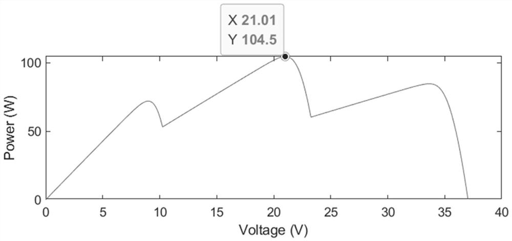
[0003] Under partial shadow conditions, the P-V curve of photovoltaic power generation shows multi-peak changes. The constant voltage method needs to work and under specific lighting conditions. For partial shadow conditions, the tracking accuracy is poor and the power loss is large; the disturbance observation method and the conductance increment method are for single peak The maximum power tracking accuracy under the P-V curve is high, but for the multi-peak P-V curve under partial shadows, only the first power peak point can be tracked, but the subsequent power peak points cannot be tracked, and it will fall into a local optimal situation. As a result, the maximum photovoltaic energy cannot be obtained, and the power generation efficiency is low; while some intelligent algorithms such as particle swarm optimization algorithm, artificial bee colony optimization algorithm, and random leapfrog algorithm can track the global optimum, but their parameter settings are complicated, and there is a certain probability of falling into local optimum

Method used


Image

  • Maximum power point tracking method under local shadow condition
  • Maximum power point tracking method under local shadow condition
  • Maximum power point tracking method under local shadow condition

Examples


Embodiment

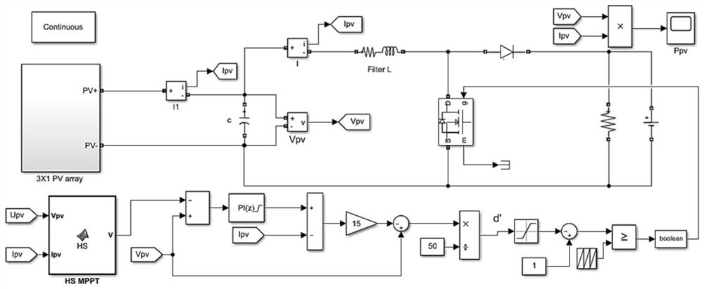
[0041] The present invention relates to a maximum power point tracking method under partial shadow conditions. The method is implemented based on an adaptive harmony search algorithm. In this embodiment, a photovoltaic cell model, a boost circuit model, and an HS-based MPPT controller model are first established through software. Among them, the photovoltaic cell model and the boost circuit model are prior art. The principle of the MPPT controller model based on HS is as follows: it is composed of the HS algorithm code, the voltage outer loop current inner loop comparison module, and the duty cycle conversion module. pv Make a difference comparison to form a voltage outer loop, and the difference is adjusted by PI and then compared with the photovoltaic cell current I pv Make a difference to form a current inner loop. After making a difference, the amplification factor is 15. The value after the gain is used as the numerator, divided by the denominator 50, and d' is output. T...


PUM


Abstract

The invention relates to a maximum power point tracking method under a local shadow condition, which comprises the following steps of: 1) constructing a photovoltaic cell model, a booster circuit model and a controller model based on a harmony search algorithm by combining current-voltage characteristics of a photovoltaic array under the local shadow; 2) initializing parameters of a self-adaptive harmony search algorithm, initializing a harmony memory bank, taking an optimized initial voltage value as harmony, generating a new harmony vector, and further obtaining an updated voltage; 3) updating the harmony vector in the harmony memory bank; and 4) judging whether an algorithm termination standard is reached or not, if so, outputting the optimal voltage and tracking the global maximum power point, otherwise, continuing to generate a new harmony vector and updating the harmony memory bank until the algorithm termination standard is reached. Compared with the prior art, the method has the advantages of improving the tracking speed and precision, improving the solar energy utilization rate and the like.

Description

technical field [0001] The invention relates to the technical field of photovoltaic power generation, in particular to a maximum power point tracking method under partial shadow conditions. Background technique [0002] With the development of society, energy and environmental issues are becoming more and more prominent, solar energy has a good application prospect as a renewable energy. However, the photoelectric conversion efficiency of photovoltaic cells is low, and the output power has a great relationship with the intensity of sunlight and the ambient temperature, which has obvious nonlinearity. It is necessary to connect a maximum power point tracking (MPPT) circuit between the photovoltaic device and the load. Give full play to the efficacy of photovoltaic cells. At present, the commonly used MPPT control algorithms include constant voltage tracking control method, perturbation and observation method, and conductance increment method. [0003] Under partial shadow c...

Claims


Application Information

Patent Timeline
IPC IPC(8): G05F1/67
CPCG05F1/67Y02E10/56
Inventor 梁智超李梦达郑旭彬姚林萍
Owner SHANGHAI DIANJI UNIV
Learn More