MPO interface-based double-fan-in and fan-out multi-channel optical module

A multi-channel, optical module technology, applied in the field of optical modules, can solve problems such as interface density bottlenecks, achieve cost optimization, reduce manufacturing difficulty, and increase the effect of external channel density

Active Publication Date: 2021-09-24
YANGTZE OPTICAL FIBRE & CABLE CO LTD
View PDF19 Cites 2 Cited by
  • Summary
  • Abstract
  • Description
  • Claims
  • Application Information

AI Technical Summary

Problems solved by technology

With parallel schemes, interface density can become the main bottleneck
With the wavelength division multiplexing scheme, the number of wavelengths of the laser needs to be increased, and the wavelength interval must be reduced accordingly. The resulting problems of cost and crosstalk will also become the bottleneck of high channel density optical modules.

Method used


Image

  • MPO interface-based double-fan-in and fan-out multi-channel optical module
  • MPO interface-based double-fan-in and fan-out multi-channel optical module
  • MPO interface-based double-fan-in and fan-out multi-channel optical module

Examples


Embodiment 1

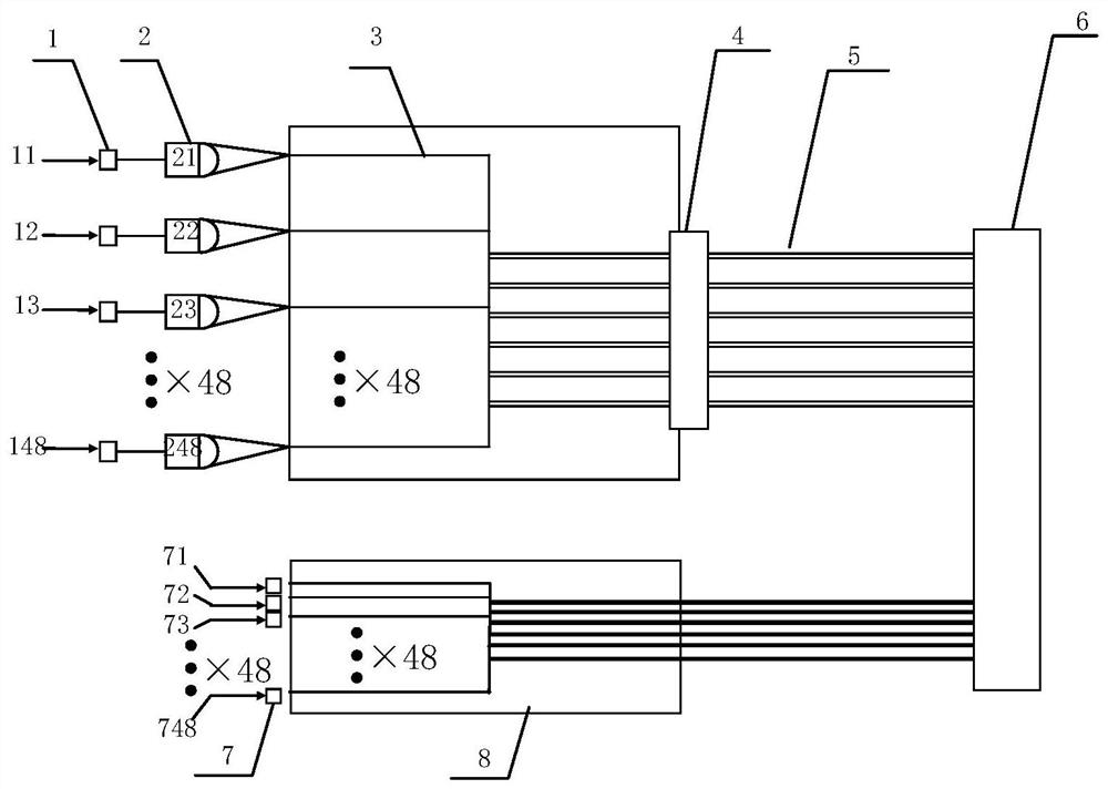
[0027] Such as figure 1 , figure 2 , image 3 and Figure 4 As shown, a new multi-channel optical module includes a 48-channel LD module 1, a 48-channel 8-core optical fiber fan-in device 3, an 8-core optical fiber array 4, and a 48-channel 8-core optical fiber array arranged in sequence along the optical axis. The 8-core optical fiber 5 (the core number is 51-58) coupled with the output ends 349-354 of the fan-in device, and the 12-core 8-core optical fiber MPO connector 6 connected with the 8-core optical fiber.

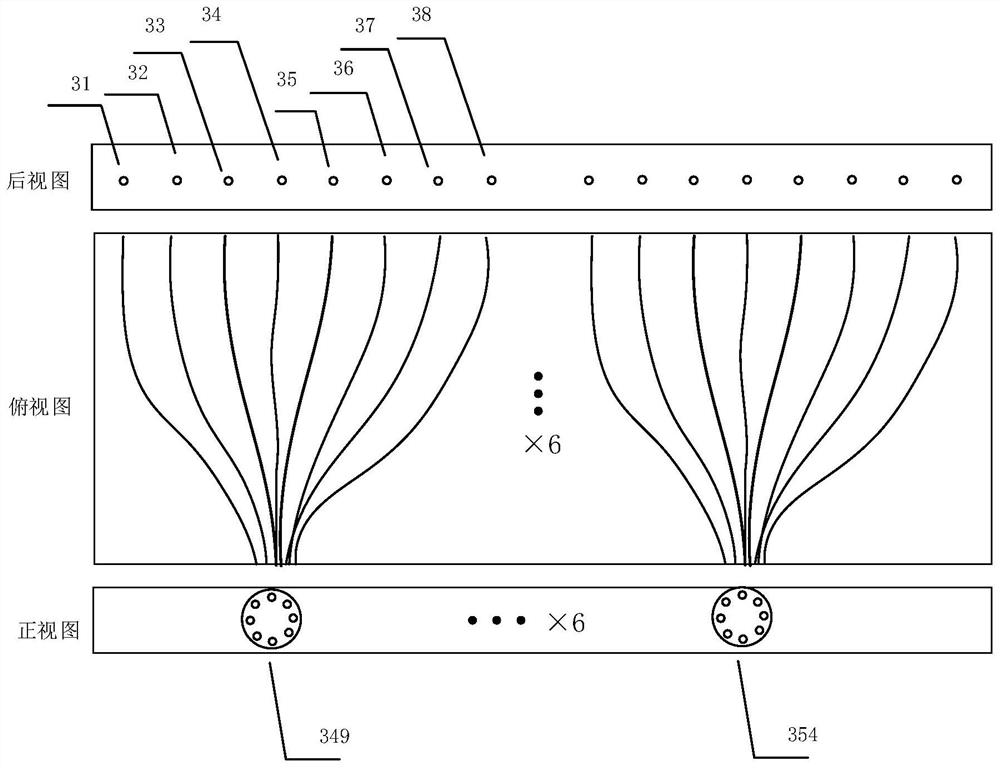
[0028] Among them, there are 48 first focusing lenses 2 respectively corresponding to the 48 channels of the laser module between the 48-channel laser module and the input end of the 48-channel 8-core optical fiber fan-in device, numbered 21, 22, 23... 248, used to converge and couple the 48 divergent light sources from the LD module to the 48 input ports 31, 32, 33...348 of the fan-in device, and enter 6 8-cores from the output terminals 349-354 of the fan-in ...

Embodiment 2

[0031] The number of lasers in the laser array in embodiment 2, the number of detectors in the detector array, the number of cores of the multi-core optical fiber and the channel number of fan-in and fan-out devices are all the same as the relevant numbers in embodiment 1, and the number of lasers and detectors The arrangement is a 2*24 rectangular arrangement.

Embodiment 3

[0033] The number of lasers in the laser array, the number of detectors in the detector array, the number of cores of the multi-core optical fiber and the number of channels of the fan-in and fan-out devices in the third embodiment are all twice the relevant numbers in the first embodiment.


PUM


Abstract

The invention discloses a double-fan-in and fan-out multi-channel optical module based on an MPO interface and belongs to the technical field of optical modules. The optical module comprises an LD module with N lasers, a multi-core optical fiber fan-in device with N input ports and N / M output ports, N / M multi-core optical fibers which are coupled with the output ports of the multi-core optical fiber fan-in device and are provided with M cores, and an N / M-core and M-core optical fiber MPO connector which is connected with the N / M multi-core optical fibers, wherein the LD module, the multi-core optical fiber fan-in device, the N / M multi-core optical fibers and the M-core optical fiber MPO connector are sequentially arranged along the direction of an output optical axis; the optical module further comprises an N / M-core M-core optical fiber MPO connector, N / M multi-core optical fibers and the multi-core optical fiber fan-out device which are sequentially arranged in the direction of the input optical axis, the N / M multi-core optical fibers are connected with the MPO connector and provided with M cores, and the multi-core optical fiber fan-out device is provided with N / M input ports and N output ports. The high-channel-density optical module can save optical fibers and wiring space, has ultrahigh interface density, can use lasers with the same wavelength, and is better in cost.

Description

technical field [0001] The invention belongs to the technical field of optical modules, and more specifically relates to a dual fan-in and fan-out multi-channel optical module based on an MPO interface. Background technique [0002] At present, high-speed optical modules mainly include SR4, PSM4, SR8, and SR16 for parallel transmission, and CWDM4, LR4, ER4, FR8, LR8, and ER8 for wavelength division multiplexing transmission schemes. Parallel transmission uses parallel transmission of multiple optical fibers to achieve high-speed transmission of a single module. For example, SR4 and PSM4 use 4 optical fibers to receive light and 4 optical fibers to emit light to realize 8-channel transmission and reception. SR8 needs to use 8 receptions and 8 transmissions, a total of 16 optical fibers for parallel transmission, and so on. The parallel solution needs to use high-density MPO connectors to connect with optical modules. The higher the number of channels, the higher the density ...

Claims


Application Information

Patent Timeline
Patent Type & Authority Applications(China)
IPC IPC(8): G02B6/42G02B6/26H04B10/40
CPCG02B6/4206G02B6/262H04B10/40
Inventor 李颖田巧丽姚钊邓兰毛明锋褚俊沈磊张磊兰小波
Owner YANGTZE OPTICAL FIBRE & CABLE CO LTD
Why Eureka
Try Eureka