Miniaturized filter

A filter and cavity technology, which is applied in the field of filters, can solve the problems of large size, many types of materials, and heavy weight of the filter, and achieve the effect of simple welding process, few types of materials, and simple structure

Pending Publication Date: 2021-09-24
TONGYU COMM INC
View PDF0 Cites 2 Cited by
  • Summary
  • Abstract
  • Description
  • Claims
  • Application Information

AI Technical Summary

Problems solved by technology

With the continuous development of modern communication technology, there are higher and higher requirements for the miniaturization of components such as duplexers, combiners, and filters. The existing duplexers, combiners, and filters are large in size , heavy weight, many types of materials, complex assembly, high price, etc., are becoming more and more unsuitable; while ceramic dielectric filters have small size, easy assembly, good electrical performance index insertion loss, and high echo consistency of the same batch advantages, but the ceramic dielectric filter also has the following disadvantages: material selection is difficult; ceramic dielectric firing process is complex, and the yield is low; the consistency between batches is poor, such as phase, amplitude, etc.; remote suppression Poor performance, almost harmonics appear near the passband, which is not conducive to engineering applications
Therefore, there is an urgent need for a miniaturized filter to solve the problems of existing filters such as large size, heavy weight, many types of materials, complex assembly, and high price.

Method used


Image

  • Miniaturized filter
  • Miniaturized filter
  • Miniaturized filter

Examples


Embodiment 1

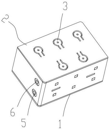
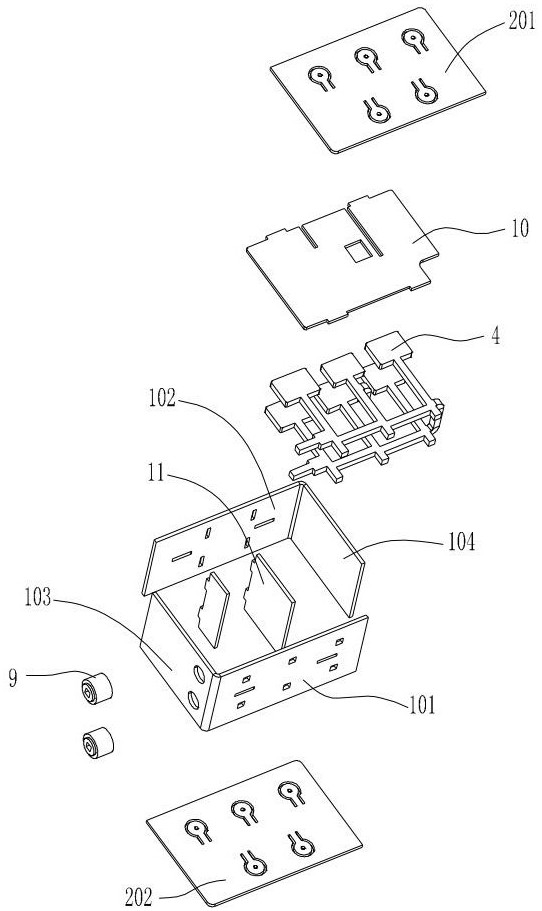
[0028] A miniaturized filter such as figure 1 and figure 2 As shown, it includes a cavity 1 made of metal material, the top and bottom of the cavity are covered with a debugging cover 2, a plurality of coupling tuning elements 3 are arranged on the debugging cover, and an integrated The integrated resonant piece 4 is formed by bending a single resonant piece or splicing a plurality of resonant pieces. One end of the integrated resonant piece is bent in a direction close to the other end, and its two ends have respectively The input port 5 and the output port 6 are arranged through the cavity 1 and both are arranged on the same end surface of the cavity. Therefore, the input and output of the transmission signal can be realized on the same plane, and the signal transmission structure becomes simpler.

[0029] Both the input port 5 and the output port 6 are boss-shaped structures 8, and the connection between the two boss-shaped structures and the cavity is provided with a su...

Embodiment 2

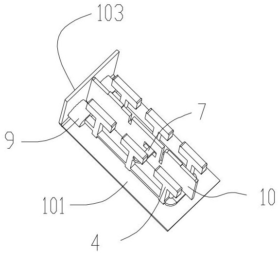
[0032] Such as image 3 and Figure 4 As shown, the difference between this embodiment and Embodiment 1 is that the inside of the cavity is also provided with at least one partition 10 arranged in the horizontal direction, and the partition 10 divides the inside of the cavity into a multi-layer structure, and is integrated The chemical resonance plate is located in one layer of the structure. Further, several clamping blocks are integrally arranged at the peripheral edge of the partition 10, bayonets corresponding to the several clamping blocks are provided on the side wall of the cavity, and the partition is set by the clamping blocks. In the bayonet, the partition 10 and the cavity 1 are connected by welding. Through the setting of the partition plate 10, the filter is separated into a multi-layer structure, so that the signal transmission channel can be realized more flexibly.

[0033] The side wall of the cavity 1 is also provided with a plurality of supporting medium p...

Embodiment 3

[0035] The difference between this embodiment and Embodiment 2 is that the bending angle of one end of the integrated resonant piece 4 is 180°, and the input port 5 and the output port 6 are arranged symmetrically. When the bending angle of one end of the integrated resonant piece 4 is At 180°, the input port and the output port are distributed up and down, as a preferred embodiment of the present invention, such as figure 2 As shown in , the input port 5 is located directly above the output port 6. The signal input and output end faces of the filter can be directly bonded and welded to the surface of the next device, or a connector can be used to transfer the signal input and output.


PUM


Abstract

According to the miniaturized filter provided by the invention, the signal transmission is carried out by directly penetrating through the surface of the filter through the integrally formed resonance piece and welding, so that auxiliary transmission devices such as a connector, a connecting piece and a connecting rod are not needed; meanwhile, 180-degree (not limited to 180-degree) bending is carried out on the integrally-formed resonance piece, half of the space of the filter is saved, a signal input port and a signal output port are formed in the same plane, signal transmission becomes simple, and the follow-up assembling and welding process is simpler. Moreover, the sheet-shaped structure is processed, cut and bent to form the cavity shell, the separation ribs and the integrated resonance piece are arranged in the cavity, assembly is carried out, and laser welding forming is carried out, so that the side wall of the filter is very thin, and the weight is light; in conclusion, the filter has the advantages of being smaller in size, lighter in weight, fewer in material types, simpler in structure, more convenient to debug and the like.

Description

technical field [0001] The invention belongs to the technical field of filters, and in particular relates to a miniaturized filter. Background technique [0002] With the wide application and development of communication technology, the requirements for communication equipment are getting higher and higher. Therefore, the development of filters to be more miniaturized, lightweight and integrated has gradually become a future development trend. In the case of limited cavity size, the coaxial cavity filter cannot be made smaller and lighter in terms of volume and weight due to its own material and processing technology requirements. In the rapidly developing communication equipment, due to the increase in the number of transmission and reception channels of the equipment, more filters need to be equipped for the transmission and reception channels of the equipment. In order to reduce the space occupied by a large number of filters, the miniaturization of the filter is the curr...

Claims


Application Information

Patent Timeline
Patent Type & Authority Applications(China)
IPC IPC(8): H01P1/207
CPCH01P1/207
Inventor 高小鹏成钢陈发剑汪宇吴中魁
Owner TONGYU COMM INC
Why Eureka
Try Eureka