

Surface micro-pit self-lubricating coating and preparation method thereof
A technology of self-lubricating coating and micro-pit, which is applied in coating, metal material coating process, etc., can solve the problems of anti-friction performance and structural wear of cladding layer, and achieve excellent lubricating performance, high bonding strength and good effect The effect of aging
- Summary
- Abstract
- Description
- Claims
- Application Information
AI Technical Summary
Problems solved by technology
Method used
Image

Examples
Embodiment 1
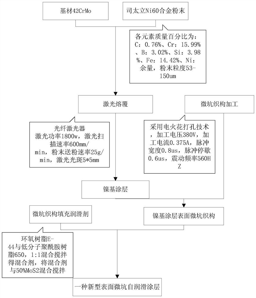
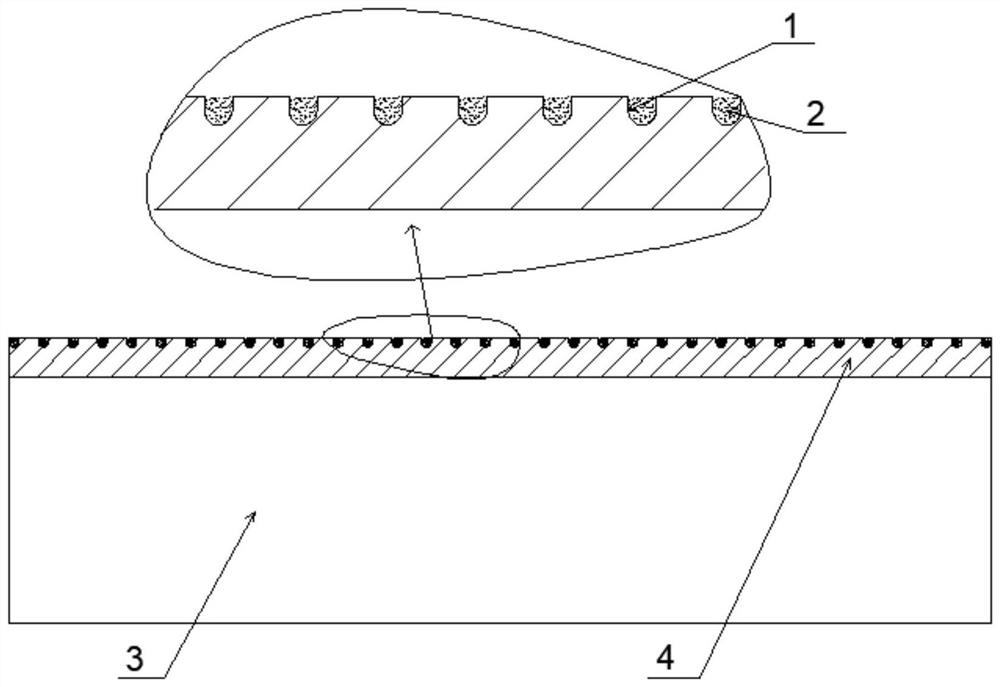
[0026] Example 1, see figure 1 and figure 2 , the preparation of a surface micropit self-lubricating coating, comprising the following steps:
[0027] (1) Preparation of coating:
[0028] 1) Substrate 3 is 42CrMo steel, the surface of which is roughened and the surface of the sample is cleaned.
[0029] 2) The powder is made of Stellite Ni60 alloy powder, mixed evenly in a ball mill, and dried. The chemical composition and mass percentage of each element of the powder are: C: 0.76%, Cr: 15.99%, B: 3.02%, Si: 3.98%, Fe : 14.42%, Ni: balance, powder particle size 53-150um.
[0030] 3) Laser cladding coating on the surface of the alloy, the alloy powder is blown to the surface of the alloy steel by coaxial powder feeding method and using the protective gas as the powder carrier gas.
[0031] 4) The coating is prepared by laser cladding, the laser power is 1800w, the laser scanning rate is 600mm / min, the powder feeding rate is 25g / min, the laser spot is 5*5mm, and the coating...
Embodiment 2
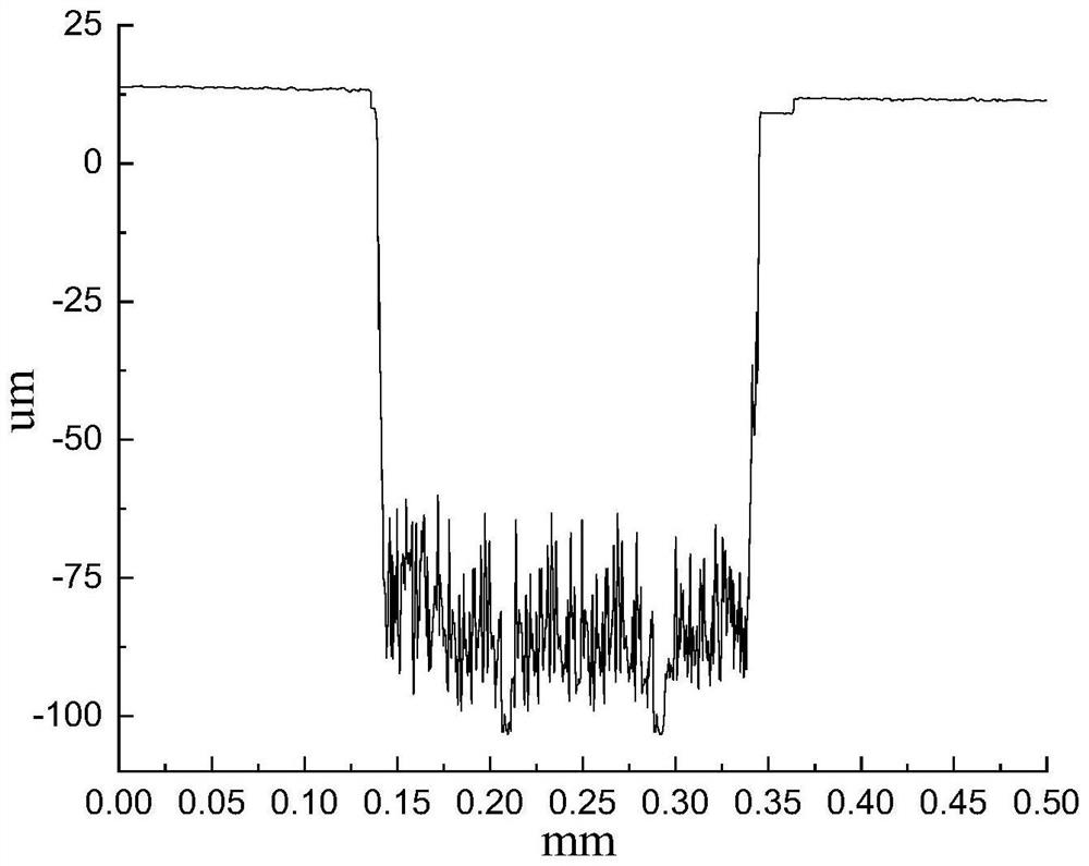
[0051] The difference between embodiment 2 and embodiment 1 lies in that: in step (2), electric discharge drilling technology is used to process micropits on the surface of the coating, and the size of the micropits array is 200um in diameter, 50um in depth, and 500um in spacing. Others are with embodiment 1.
PUM
| Property | Measurement | Unit |
|---|---|---|
| Surface roughness | aaaaa | aaaaa |
| Diameter | aaaaa | aaaaa |
| Width | aaaaa | aaaaa |
Abstract
Description
Claims
Application Information