Silicon optical accelerometer based on MZI interference system and preparation method thereof

A technology of accelerometer and interference system, which is applied in the field of silicon optical accelerometer and its preparation based on MZI interference system, which can solve the problems of complex twisting interferometer and difficult process, and achieve the effect of strong anti-interference ability and high sensitivity

Inactive Publication Date: 2021-10-01
OTN INTELLIGENT TECH (SUZHOU) CO LTD
View PDF0 Cites 1 Cited by
  • Summary
  • Abstract
  • Description
  • Claims
  • Application Information

AI Technical Summary

Problems solved by technology

[0003] The torsion interferometer type optical accelerometer has been reported. It uses a mass block torsion MZI interference structure to measure the waveguide through the interference of light and finally completes the measurement of acceleration. However, the torsion interferometer is more complicated and the process is difficult to realize.

Method used


Image

  • Silicon optical accelerometer based on MZI interference system and preparation method thereof
  • Silicon optical accelerometer based on MZI interference system and preparation method thereof
  • Silicon optical accelerometer based on MZI interference system and preparation method thereof

Examples


Embodiment 1

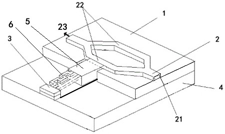
[0065] This embodiment provides a kind of uniaxial silicon optical accelerometer based on MZI interferometric system, such as figure 1 and figure 2 shown, including:

[0066] The base layer 4 is made of silicon material;

[0067] The top layer 1 is arranged on the base layer 4;

[0068] A fixed anchor 3 is fixedly arranged on the base layer 4;

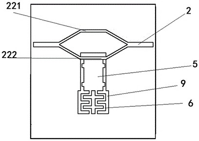
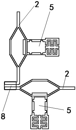
[0069] The MZI interference structure 2 is arranged on the top layer 1 and includes: an input end 21 and an output end 23, and a fixed waveguide 221 and a measurement waveguide 222 which are connected to the input end 21 and the output end 23 and arranged in parallel;

[0070] The mass 5 is connected to the measuring waveguide 222 at the top, one end is connected to the fixed anchor 3 through the first cantilever beam 61, and the other end is connected to the fixed anchor 3 through the second cantilever beam 62 located below the measuring waveguide 222, and the middle or bottom of the second cantilever beam 62 is Has an oxide laye...

Embodiment 2

[0087] This embodiment provides a method for preparing a uniaxial silicon optical accelerometer based on an MZI interference system, comprising the following steps:

[0088] S1: Take an SOI wafer, the SOI wafer includes a base layer 4, a top layer 1 and an oxide layer between the base layer 4 and the top layer 1;

[0089] S2: Etching is performed on the top layer 1 to form an MZI interference structure 2, the MZI interference structure 2 includes: an input end 21 and an output end 23, and a fixed waveguide 221 and a fixed waveguide 221 that is connected in parallel to the input end 21 and the output end 23 at the same time measuring waveguide 222;

[0090] S3: continue to etch the top layer 1, etch the cavity 81 around the mass block 5 and the first cantilever beam 61 to form the corresponding shapes of the mass block 5 and the first cantilever beam 61;

[0091] S4: Etch from the bottom of the base layer 4 at the position corresponding to the cavity to be etched around the ma...


PUM


Abstract

The invention relates to a silicon optical accelerometer based on an MZI (Mach Zehnder Interference) system, light is incident from an input end, when an inertia force is applied, a mass block supported by a cantilever beam also displaces, the mass block pushes a measurement waveguide to generate strain, and due to a photoelastic effect and a strain effect, the transmission phase of the light in the measurement waveguide shifts with the movement of the mass. The light of the fixed waveguide and the measurement waveguide generates MZI interference in front of the output end, and the light intensity of the output end is measured to achieve the purpose of extracting the measured acceleration signal. The optical accelerometer has the advantages of high sensitivity and strong anti-interference capability, and can adapt to severe environments or environments with precision measurement requirements.

Description

technical field [0001] The application belongs to the technical field of photon sensors, and in particular relates to a silicon optical accelerometer based on an MZI interference system and a preparation method thereof. Background technique [0002] Accelerometers are important test components for inertial navigation, guidance and control systems, and are widely used in missile guidance, aircraft navigation, attitude control of artificial satellites, brake system control, vibration measurement of large electrical equipment, and petroleum seismic exploration. In recent years, with the development of micromachining technology and integrated optics technology, micro-opto-electromechanical (MOEMS) accelerometers, which have significant advantages such as integration and miniaturization of micro-mechanical accelerometers, high precision of optical accelerometers, and anti-electromagnetic interference, have been obtained. Extensive research at home and abroad. [0003] The torsio...

Claims


Application Information

Patent Timeline
Patent Type & Authority Applications(China)
IPC IPC(8): G01C21/16G01P15/03G01P1/00
CPCG01C21/16G01P15/03G01P1/00
Inventor 刘晓海吴盟
Owner OTN INTELLIGENT TECH (SUZHOU) CO LTD
Why Eureka
Try Eureka